
An overview of the hyperloop system, through a description of its operational concept, its subsystems, functions and specifications
Disclaimer
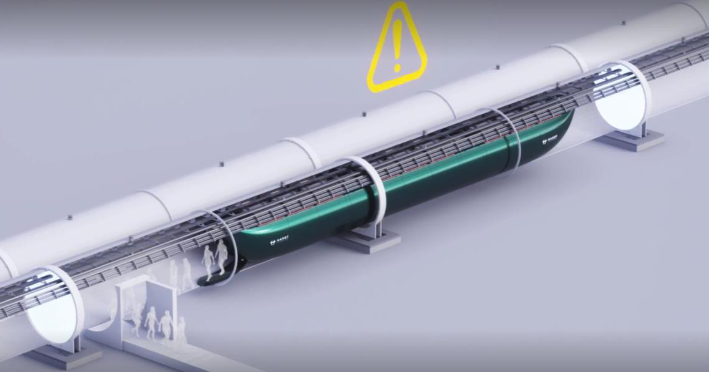
This document describes the vision of the hyperloop as proposed by Hardt Hyperloop at the time of writing. As hyperloop technology is still under development, the design choices presented here are preliminary and subject to change.
JTC-20
Functional Architecture for Hyperloop System Design
Alignment Functions and Systems
Following the JTC-20 standard for the Functional Breakdown Architecture
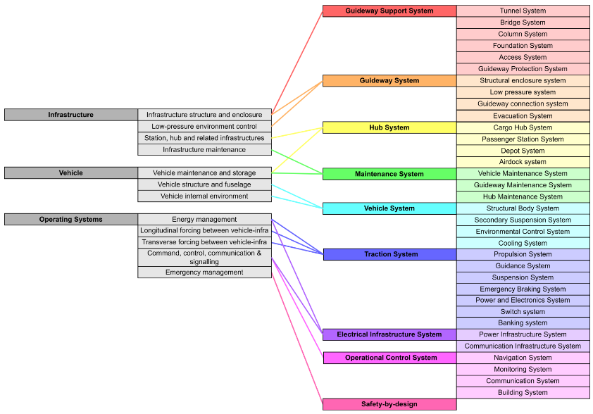
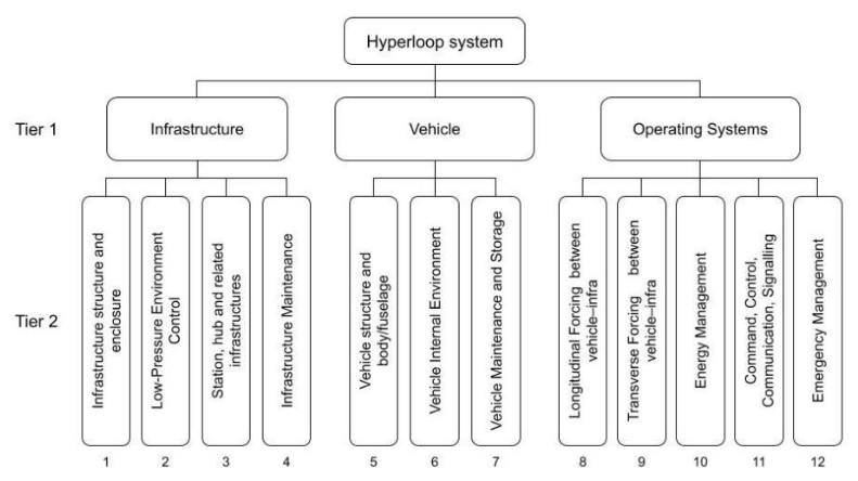
Hyperloop System – Level 1 and functions
Hyperloop System | Guideway System | Provides the vehicles with an enclosed, low-pressure environment that guides them along a path. |
Guideway Support System | Supports and protects the guideway and connects it with the ground. | |
Traction System | Moves and positions the vehicle within the guideway system during nominal operations. | |
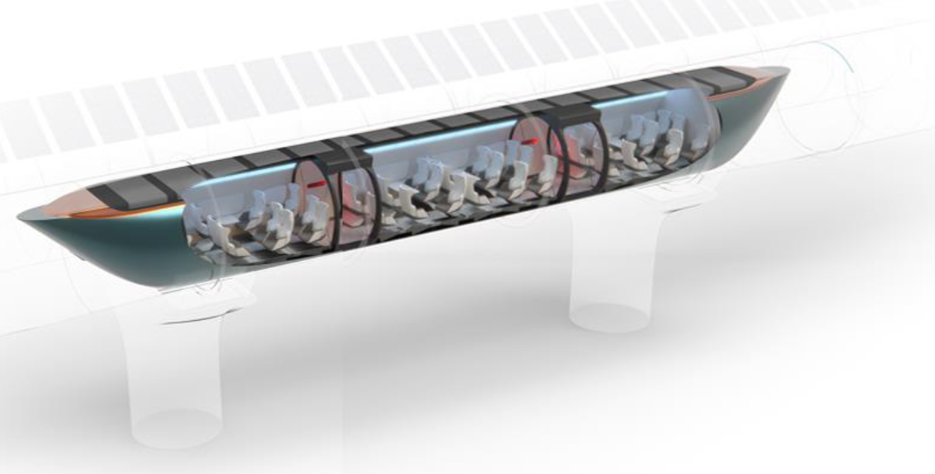
Vehicle System | Provides a comfortable pressurized environment for the payload to be transported throughout the system. | |
Operational Control System | Provides traffic management and controls the infrastructure, hubs and vehicles within the system. | |
Electric Infrastructure System | Supplies the system with power and provides a communication network. | |
Maintenance System | Ensures the system’s integrity and ability to meet operability standards. | |
Hub System | Processes, (un-)loads cargo and vehicles, or (dis-)embarks passengers after arrival at a hub. |
Safety
Hyperloop must be safe, which is why all safety cases are considered according to the Safety Concept. Some system failures cannot be solved be fail-safe design, a safe-life approach or other means of failure mitigation such as redundancy or safety factors. For these cases, specific solutions are required. Several of the major safety cases and their corresponding solutions are presented below.
Function | Hazard | Risk Mitigation |
Safe pathway for vehicle | Obstruction of the vehicle path by an immediate stop of another vehicle or a defect in the guideway | Emergency brake and sufficient headway |
Accelerate / decelerate | Loss of braking functionality | Emergency brake |
Vehicle suspension | Loss of levitation functionality | Back-up catch system |
Vehicle guiding | Collision between vehicle and switch due to guidance failure | Back-up switch system |
Provide safe vehicle environment | Pressure loss in vehicle due to structural failure | Rapid guideway re-pressurization |
Provide safe environment | Vehicle and/or guideway is unsafe (e.g. fire) | Evacuation system |
Some of the solutions merit a specific system. These systems are the following and are discussed in more detail further in the document:
- Emergency braking system
- Catch system
- Switch guard
- Evacuation system
Safety concept
Safety is one of the key system properties for the final acceptance of the hyperloop, not only by the regulators but most importantly by the general public. The safety concept of the hyperloop is that a safe-by-design hyperloop system will be developed following the principles of system safety *.
Safe-by-design
Following the safe-by-design vision, safety must be guaranteed in the design.
“Hyperloop is a safe-by-design system that ensures, in an integrated system-manner, that hazards to human life, environment, public-private property and hyperloop infrastructure are prevented, eliminated and controlled.”
Objectives
- The priority is to ensure safety to human life, transported goods, environment, public/private property and hyperloop infrastructure (in that specific order).
- Secondary to this is finding a way to achieve this safety whilst also guaranteeing high availability of the system and commercial viability.
Process
The safe-by design process for hyperloop follows the product development phases within its integral iterative approach. A safety assessment process is defined to structure the safe-by-design approach and integrated into the product life-cycle. This process is based on common well-known practices [ISO31000, EN50126, SAE ARP 4761,IEC61508] follows certain steps following the systems life-cycle.
* System safety considers engineering as well as management principles, criteria and techniques to consider all safety aspects throughout all phases in the system life cycle.
0 - The Hyperloop System
Subsystems and functions - Level 1
- Guideway System provides the vehicles with an enclosed, low-pressure environment that guides them along a path.
- Guideway Support System support and protects the guideway and connects it with the ground.
- Traction System moves and positions the vehicle within the guideway system during nominal operations.
- Vehicle System provides a comfortable pressurized environment for the cargo to be transported through the system.
- Operational Control System schedules and controls the infrastructure, hubs and vehicles within the system.
- Electrical Infrastructure System supplies the system with power and provides communication network.
- Maintenance System ensures the system's integrity and ability to meet operability standards.
- Hub System processes, (un-)loads cargo and vehicles, or (dis-)embarks passengers after arrival at a hub.
Characteristic | Performance |
Guideway capacity | 11.000 Pax/h/dir (at 700 kph) (multipliable with platooning) |
Vehicle capacity | 40 Passengers ; 12 Euro Pallets |
Design capacity | 1000 kph max. ; 700 kph cruise |
Operational pressure | 1 mbar |
Operating temperature | -25 °C to 75 °C (can be tailored to location) |
Average energy consumption | 42 Wh/pax-km - determined for a reference route including vacuum energy consumption (70% occupancy, 60% cruising & 40% acc. & dec.) |
Vehicle power consumption | 3.3 MW at max. acceleration ; 665 kW at cruising speed (700 kph) |
Propulsion power | 3 MW |
Levitation airgap | 15 mm |
Vehicle length | 24 m |
Vehicle Internal diameter | 2.5 m |
Tube internal diameter | 3.5 m |
Blockage ratio | 60% |
Guideway material | Steel |
Substructure material | Concrete |
Longitudinal acceleration | 0.11 g or 1.1 m/s² average ; 0.2 g or 2.0 m/s² peak |
Deceleration | Operational braking = 0.15 g or 1.5 m/s²
Emergency braking = 0.8 g or 8 m/s² |
Cant (guideway) | 13° |
Tilt (vehicle) | 6° (technology underdevelopment, expected between 0° and 13°) |
Banking angle | 19° (depending on tilting technology, between 13° and 26°) |
Equivalent angle deficiency | 7.5° (depending on tilting technology, between 0° and 13°) |
(uncompensated) Lateral acceleration | 0.15 g or 1.5 m/s² |
Total corner acceleration | 0.5 g or 5.0 m/s² (made possible by 19° banking with 0.15 g max. lateral acceleration on pax) |
Min. turning radius | 200 m |
Max. Lateral jerk | 0.05 g/s in linear guideway ; 0.2 g/s in switch box |
Max. Longitudinal jerk | 0.1 g/s or 1.0 m/s² |
Max. Gradient | 10% |
Max. Upward acceleration | 0.06 g or 0.6 m/s² |
Max. Downward acceleration | 0.12 g or 1.2 m/s² |
1 - Guideway System
CORE FUNCTION - Provide the vehicles with a pathway in an enclosed low-pressure environment.
Subsystems and functions - Level 2
- Structural Enclose System provides the vehicles with a closed off environment and forms the structural backbone for systems that are connected to the guideway.
- Low Pressure System creates a low pressure inside the structural enclosure system
- Guideway Connection System connects the structural enclosure system internally and to the guideway support system.
- Evacuation System safely evacuates passengers, cargo and vehicles from the system in case of an emergency.
Characteristic | Performance |
Capacity | 11.000 Pax/h/dir (at 700 kph) (multipliable with platooning) |
Blockage ratio | 60% |
Linear pipe diameter | Internal Diameter = 3.5 m |
Pipe thickness | 20 mm |
Span | 20 m |
Min. Turning radius | 200 m (vehicle kinematics and packaging) |
Material | Steel (although concrete is also possible) |
Operational pressure | 1 mbar |
Intermediate exit distance | 500 m |
Segmentation time | 30 s |
Re-pressurization time | 60 - 90 s to 1 bar |
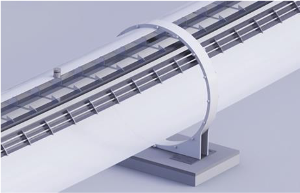
1.1 Structural enclosure system
CORE FUNCTION - Provide the vehicles with a closed-off environment and form the structural backbone for systems that are connected to the guideway.
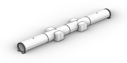
The structural enclosure is made up of 20-meter steel pipe segments with a welded center stiffener and flanges at the end. The pipes provide a strong, secure and weatherproof barrier between the pipe’s interior and exterior environment. It also provides the structural backbone for the systems that are connected to the guideway.
To ensure the guideway’s structural integrity, the guideway and its connected system must always remain within its tolerances. To this end, the structural enclosure is designed to handle a combination of critical load cases. The major ones being:
- Low pressure load created by the pressure difference between the internal and external environment, acting on the guideway structure.
- Self weight of the infrastructure, which is referred to as a permanent load.
- Vehicle loads which includes the vehicle weight and dynamic loads on the infrastructure during operational and safety cases.
- Environmental loads which includes all external factors that are acting on the infrastructure (e.g. wind, snow, earthquakes and soil displacements)
The structural design is optimized based on a combination of defining load cases. In principle this is done in the following ways:
- The use of a circular load bearing structure.
- The choice of material and construction method
- Thickness of the tube and the use of stiffeners
- Optimizing this span of tube segments
* Finite Element Modelling (FEM) is used as a tool to optimize the structural design. The structural design has been verified and validated multiple times through the development of test setups and prototypes.
Characteristic | Performance |
Span | 20 m |
Linear pipe weight (20m) (one-way) | 35 tons (excl. flanges and tracks) |
Switch pipe weight (20m) (one-way) | Avr. 50 tons (excl. flanges and tracks) |
Material | Steel |
Linear pipe diameter | Internal diameter = 3.5 m |
Linear pipe thickness | 20 mm |
1.2 Low pressure system
CORE FUNCTION - Creates and maintains a low pressure inside the structural enclosure system.
The low-pressure system uses vacuum technologies in a sealed environment to create and maintain low pressure conditions within the guideway. The sealed environment is created by limiting the inflow of air throughout the guideway. To this end, all guideway systems are designed to limit the flow of air into the tube.
The operational pressure is achieved by pumping out the air from the sealed environment. This is done with a combination Backing pumps and Booster pumps. These vacuum pump types work together to efficiently pump down and retain the low-pressure in the tube.
All values in the table below consider a one-way linear guideway.
Characteristic | Performance |
Operating pressure | 1 mbar or 100 Pa |
Pump down time | 15 hours per km |
Energy consumption | 1 kW/km for retention;
22 kW/km for pump down |
Leak rate | 660 Pa*L/s (Guideway = 50% ; Airlocks |
Intermediate pump station distance | 1 every 35 km for retention:
1 every 1 km for pump down (can be employed as mobile units) |
Pump station size | Half container for each pump combination:
L = 6.0 m ; H = 2.6 m ; W = 2.4 m |
1.3 Guideway connection system
CORE FUNCTION - Connect the structural enclosure system internally and to the guideway support system.
A variety of technologies are used to connect the guideway segments to each other and to the substructure.
- The connection between guideway segments allow for expansion and contraction of the pipe due to temperature changes. The connection between guideway segments is maintained with the use of a flexible seal and expansion joints. The gasket connections ensure that the vacuum environment is preserved.
- The connection between the guideway and the substructure is designed to transfer the forces experienced by the guideway to the substructure. These forces include the movement of the guideway due to heat expansion. These movements are supported using sliding connections between the substructure and the guideway.
- The guideway connection system is also vital to ensure that the tracks stay within the precision alignment required for high-speed travel. Misalignments can occur over time due to soil settlements or material fatigue. In such cases, the adjustable supports are used to realign the guideway and the tracks.
Characteristic | Performance |
Operational temperature | Min. = -36 °C ; Max. = 73 °C |
Thermal expansion | 20 mm per 20 m guideway segment |
Turning angle | 5.73° (required to achieve a 200 m radius with 20 m guideway sections) |
Expansion joing | 1 every guidway segment (20 mm thermal expansion)
or
1 every 4 guideway segments (80 mm thermal expansion) |
Gasket | Every guideway segment |
1.4 Evacuation system
CORE FUNCTION - To safely evacuate passengers, cargo and vehicles from the system in case of an emergency.
Characteristic | Performance |
Intermediate exit distance | 500 m |
Segmentation time | 30 s |
Re-pressurization time | 4 s to 0.063 bar (armstrong limit)
35 - 40 s to 0.6 bar (breathing without masks)
60 - 90 s to 1 bar |
Release valves | 30 per km |
Valve inlet size | 15 cm |
In the highly unlikely scenario that an emergency occurs that requires passengers to exit the vehicle and guideway, the evacuation system ensures that this can be done safely.
Evacuation process
- The vehicle is safely brought to a standstill.
- A section of the tube is sealed using segmentation doors.
- Release valves pressurize the guideway segment.*
- Passengers exit the vehicle through emergency doors at the nose and tail of the vehicle.
- Passengers are guided to the guideway’s nearest emergency exit.
* In case passengers become exposed to a pressure below the Armstrong limit, re-pressurization occurs immediately, without the vehicle coming to a standstill or segmentation.
After segmentation, some vehicles will not be able to continue on their path. These pods are then redirected to their destination. If this is not possible, the pods will be guided towards the nearest station where passengers can safely exit the vehicle.
2. Guideway Support System
CORE FUNCTION - Support and protect the guideway and connect it with the ground.
Subsystems and functions – Level 2
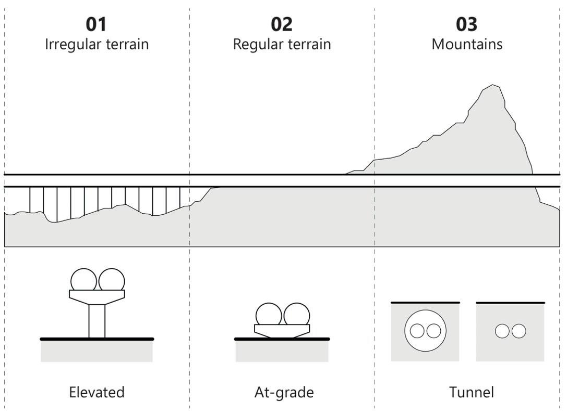
- Foundation System connect the guideway support system to the ground for support.
- Column System support the guideway system at a height of up to 10 meters and for spans of up to 20m.
- Bridge System implements the guideway system over large spans (>20m) and heights (>10m).
- Tunnel System supports the guideway system underground.
- Access System provides accessways to the guideway system.
- Guideway Protection System provide protection to the guideway system (e.g. signs and fencing).
Characteristic | Performance |
Pipe span | 20 m (Location dependent - Landscape) |
Column diameter | 2.5 m (Location dependent - Landscape) |
Column height | 5 m (Location dependent - Landscape) |
Foundation base | (Location dependent - Soil conditions) |
Tunnel | Inner diameter | Outer diameter |
One-way | 4.15 m | 5 m |
Two-way | 10 m | 11 m |
3. Traction System
CORE FUNCTION - Move and position the vehicle within the guideway system during nominal operations.
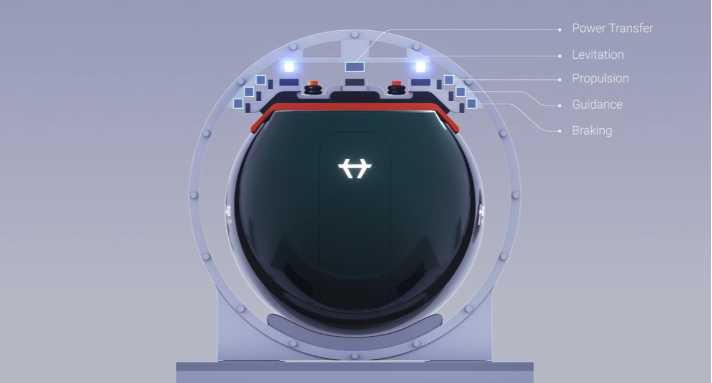
Subsystems and functions – Level 2
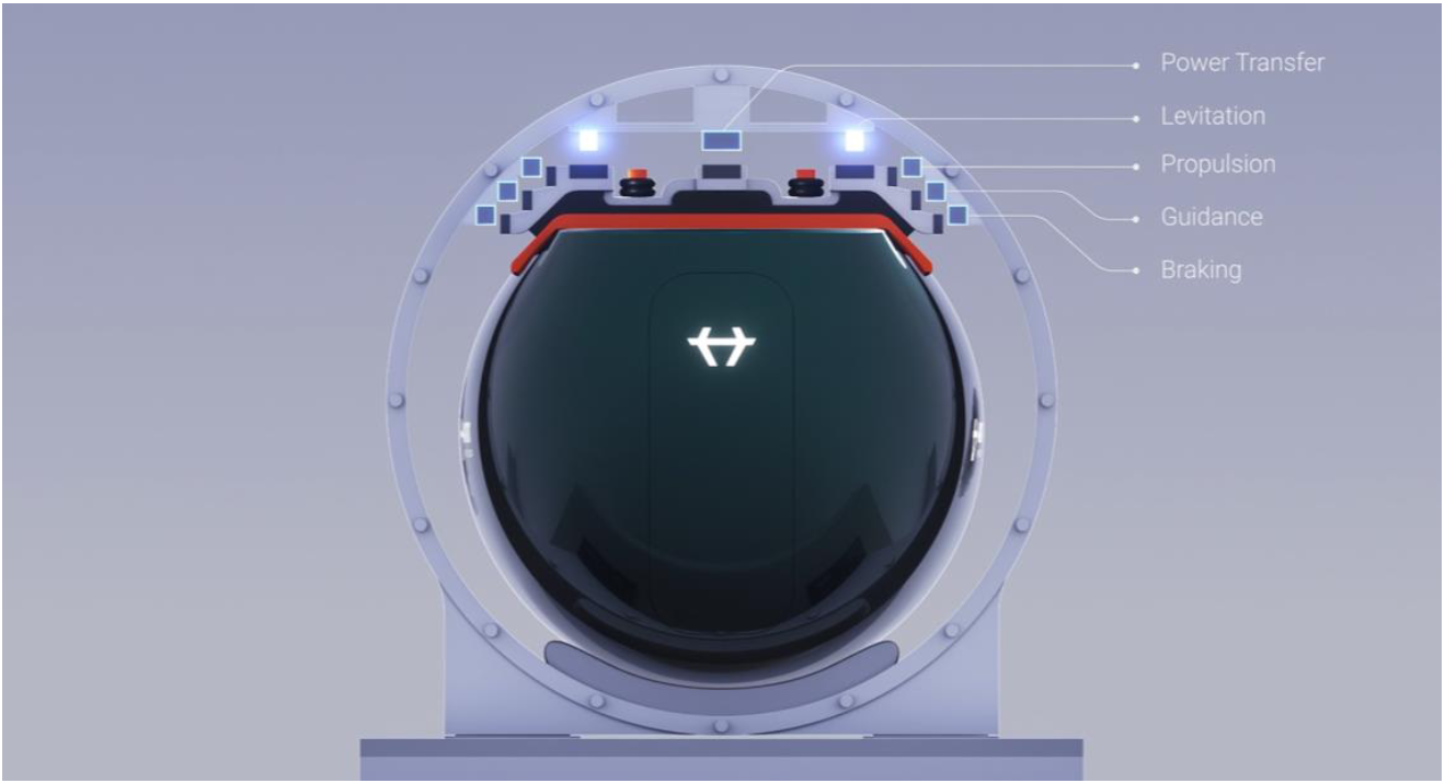
- Propulsion System accelerates and decelerates the vehicles.
- Suspension System vertically positions the vehicle in the guideway and control the vehicle’s pitch, yaw and roll.
- Guidance System horizontally positions the vehicle in the guideway and control the vehicle’s pitch, yaw and roll.
- Emergency Braking System safely brings the vehicles to a standstill in case of an obstruction or loss of braking functionality.
- Power and Electronics provide the vehicle and tractive systems with electrical power and hardware for control of the different electrical systems.
- Switching System enables vehicles to switch between pathways at high speed.
- Banking System limits the lateral forces experienced by the payload whilst cornering at high-speed.
Characteristic | Performance |
Total track weight | 10,200 kg (8 tracks of 20 m) |
Total magnets weight | 10,000 kg (propulsion, levitation, guidance & emergency braking system) |
Battery weight | 3200 kg |
Battery capacity | 640 kWh |
Propulsion power | 3 MW |
Propulsion efficiency | ~90% |
Power consumption | 3.3 MW at max. acceleration
665 kW at cruising speed (700 kph) |
Air gap | 15 mm |
Emergency braking | 0.8 g |
Total drag at cruise (700 kph) | 3100 N (Magnetic = 1650 N ; Aerodynamic = 1450 N) |
3.1 Propulsion System
CORE FUNCTION - Accelerate and decelerate the vehicles.
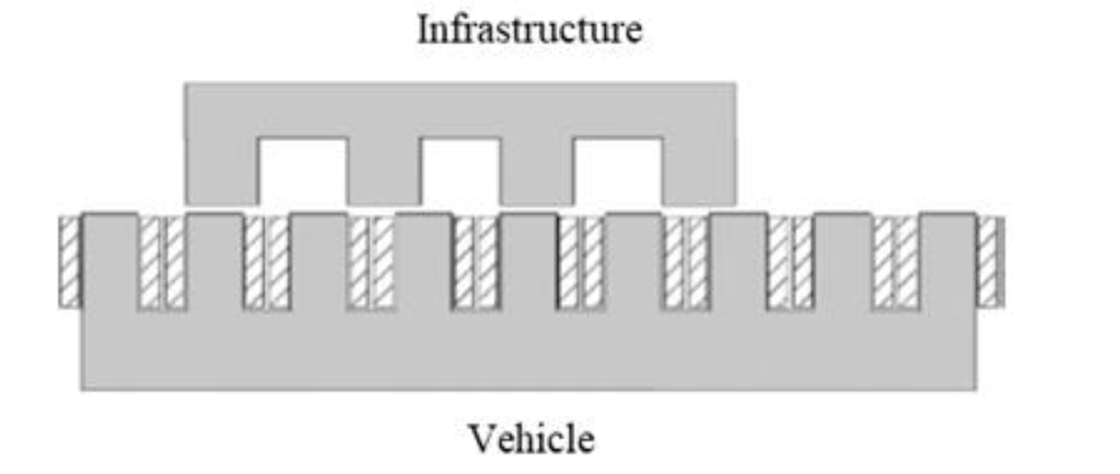
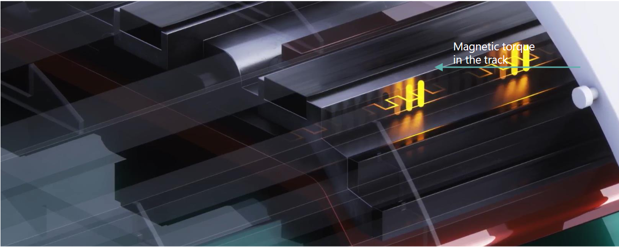
For the propulsion system a Synchronous Reluctance Motor (SRM) is used. In principle the SRM works as follows:
- The track (rotor) is made up of a series of metallic poles that are arranged to create a magnetic reluctance path.
- The motor (stator) windings generate a magnetic field by applying a current.
- The magnetic field of the motor interacts with the poles of the track, creating a torque and moving the motor along the track.
- The speed of the vehicle is regulated by adjusting the frequency of the current through the motor, which is synchronized with the position of the track.
Characteristic | Performance |
Propulsion track weight | 2800 kg (two 20 m propulsion tracks) |
Propulsion track material | Laminated steel |
Propulsion magnet weight | 1,700 kg per vehicle (28 units of 60 kg) |
Propulsion power | 3 MW |
Propulsion efficiency | ~90% |
Power consumption | 3.3 MW at max. acceleration
665 kW at cruising speed (700 kph) |
Max. acceleration | 2.0 m/s² |
Average acceleration (to 700 kph) | 1.13 m/s² (for a 25,000 kg vehicle with a 3 MW motor) |
Nominal braking | 1.5 m/s² |
Performance by speed [kph] | 100 | 200 | 300 | 400 | 500 | 600 | 700 | 1000 |
Average acceleration [m/s²] | 2.00 | 2.00 | 1.90 | 1.67 | 1.46 | 1.27 | 1.13 | 0.83 |
On-ramp length [km] | 0.2 | 0.8 | 1.9 | 3.7 | 6.6 | 11.0 | 16.7 | 46.5 |
Off-ramp length [km] | 0.3 | 1.0 | 2.3 | 4.1 | 6.4 | 9.3 | 12.6 | 25.7 |
3.2 Suspension System
CORE FUNCTION - Vertically position the vehicle in the guideway and control the vehicle’s pitch, yaw, and roll.
Levitation System
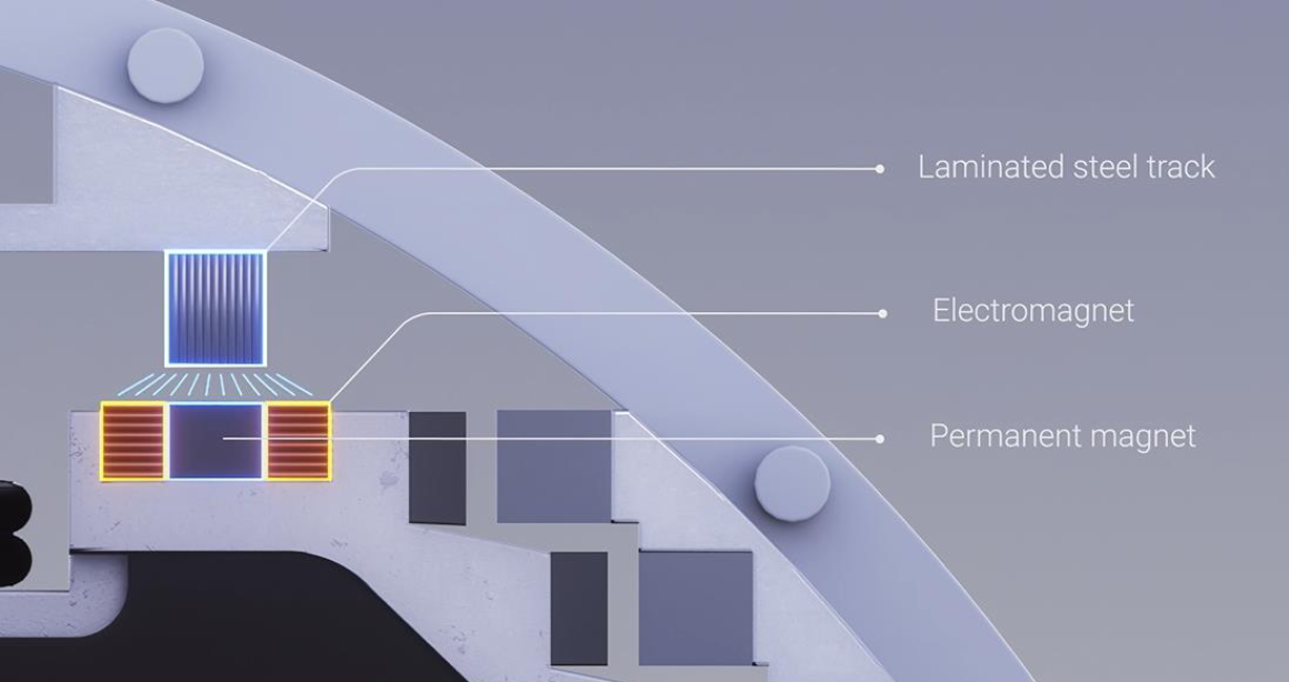
Levitation is achieved using an electromagnetic levitation system (EMS). EMS works based on attraction towards a laminated steel track and uses an active control system for stability. The attraction towards the track along the length of the vehicle aids the control of the vehicle’s pitch, yaw and roll.
EMS for levitation uses a combination electromagnets, permanent magnets and a laminated steel track to levitate. The permanent magnet creates a static magnetic field that uses no energy and does the heavy lifting of the vehicle. The electromagnet than balances the vehicle at the airgap, requiring only very little power.
The balancing is achieved through a continual control loop that changes the direction and strength of the electromagnet’s magnetic field as follows:
- If the airgap becomes too large, the magnetic field is increased, and the vehicle is pulled towards the track.
- If the airgap becomes too small, the magnetic field is decreased, and gravity pulls the vehicle away from the track
Catch system
The vehicle’s levitation system is designed to prevent the magnets from ever coming into contact with the track. In the very unlikely case that a vehicle's levitation completely fails, the vehicle will drop away from the track. In this case, a passive catch system is in place that catches the vehicle with a passive sliding mechanism. The catch system’s tracks then supports the vehicle while the emergency brake brings the vehicle to a controlled stop.
Characteristic | Performance |
Levitation track weight | 3,000 kg (two 20 m levitation tracks) |
Levitation track material | Laminated steel |
Levitation magnet weight | 3,400 kg (42 modules of 80 kg) |
Operational airgap | 15 mm |
Magnetic lift-over-weight | 10 |
magnetic lift-over-drag | 150 |
Power consumption | Negligible |
Operations | Each individual magnet operates autonomously |
Power supply | The magnets are powered by multiple batteries for redundancy |
Safety | High redundancy makes the system extremely safe |
3.3 Guidance System
CORE FUNCTION - Vertically position the vehicle in the guideway and control the vehicle’s pitch, yaw, and roll.
Magnetic guidance
Guidance is achieved using an electromagnetic guidance system (EMS). EMS works based on attraction towards a laminated steel track and uses an active control system for stability.
EMS for guidance uses a combination of electromagnets and a laminated steel track. The guidance magnets are at the sides of the vehicle and pull the vehicle either left or right towards the track. The attraction towards the track along the length of the vehicle aids the control of the vehicle’s pitch, yaw and roll.
Proper guidance along the track is ensured through a continual control loop that changes the direction and strength of the magnetic field as follows:
- If the vehicle moves to far to the right, the magnetic field on the right is decreased and on the left is increased. As a result, the vehicle is pulled towards the left.
- If the vehicle moves to far to the left, the magnetic field of the left is decreased and on the right is increased. As a result, the vehicle is pulled towards the right.
Note: the levitation system also ensures a part of the guidance, through its proclivity to follow the levitation tracks.
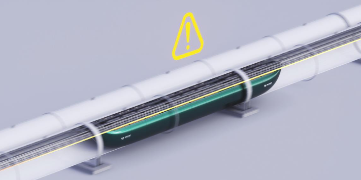
Switch guard
In case of a guidance failure in the switch, a switch guard is present to prevent collision of the vehicle with the middle of the switch (frog). The switch guard is an additional safety feature of the switch. It passively and mechanically provides a fail-safe back-up system that prevents derailment and a potential collision with the switch.
Characteristic | Performance |
Guidance track weight | 2,000 kg (two 20 m guidance tracks) |
Guidance track material | Laminated steel |
Guidance magnet weight | 1,700 kg (42 modules of 40 kg) |
Power consumption | Negligible |
Safety | Redundancy / independence |
Operation | Each individual magnet operates autonomously |
Power supply | The magnets are powered by multiple batteries for redundancy |
Safety | High redundancy makes the system extremely safe |
3.4 Emergency Braking System
CORE FUNCTION - To safely bring the vehicles to a standstill in case of an obstruction or loss of braking functionality.
The emergency braking system (EBS) is a passive fail safe braking system that works even without power. The EBS makes use of eddy current braking. Here, on-board passive magnets are deployed in close proximity to a conductive track. The result is a high magnetic drag and a steep deceleration of the vehicle.
The hyperloop vehicles are equipped with seat belts that make it possible to decelerate with up to 0.8 g. To ensure that no vehicles collide, a safe headway is always maintained. This headway is equal to the emergency braking distance for a brick-wall scenario.
Characteristic | Performance |
EBS track weight | 2,400 kg (two 20 m tracks) |
EBS magnet weight | 3,200 kg (26 units of 120 kg) |
Emergency braking | 0.8 g |
Reaction time | 1 s |
Performance by speed [kph] | 100 | 200 | 300 | 400 | 500 | 700 | 1000 |
Headway [s] | 2.7 | 4.5 | 6.2 | 7.9 | 9.7 | 13.2 | 18.4 |
Emergency braking distance [m] | 75 | 248 | 517 | 883 | 1345 | 2557 | 5100 |
3.5 Power & Electronics System
CORE FUNCTION - Provide the vehicle with electrical power and hardware for control of the different electrical systems.
Power
The vehicle’s electrical systems are powered using battery modules. To ensure safe operation, each of the vehicle’s magnets is powered by multiple batteries. The redundancy of the batteries ensure that power loss is not possible.
The batteries are charged using regenerative braking and Inductive Power Transfer (IPT). IPT is a highly efficient form of contactless charging, that uses induction to transfer power from the track to the vehicle. IPT can transfer power when the vehicle is idle and when the vehicle is traveling at high speeds. Together, the IPT and regenerative braking, drastically reduce the required on-board battery capacity, and avoid time spend waiting idly to charge.
Electronics
The electronics control the vehicles and tractive electrical systems and ensures their satisfactory operation. The main electrical systems are the levitation, guidance and propulsion systems. The modules of these systems each acts autonomously using their own flight controller. This makes the vehicle’s systems highly redundant and safe. In addition, a supervisory system oversees the subsystems and ensures that the commands of the Operational Control are followed correctly.
Characteristic | Performance |
IPT efficiency | >90% |
IPT installation | In stations and along high-speed corridors |
Vehicle range (excl. IPT) | Approx. 700 km |
Battery capacity | 640 kWh |
Battery used to 700 kph cruising | ~25% |
Battery weight | 3,200 kg |
Battery material | Lithium |
3.6 Switch System
CORE FUNCTION - Enable vehicles to switch between pathways at high speed.
Network topology
The hyperloop network has the same topology as that of highways. Here, vehicle travel at high-speed on a main line, and to join or exit the mainline the vehicles take a high-speed switch.
The topology enables direct trips between origin and destination, without slowing down or intermediate stops. The witches are the crucial component to unlock this potential of the hyperloop network.
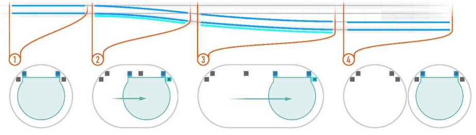
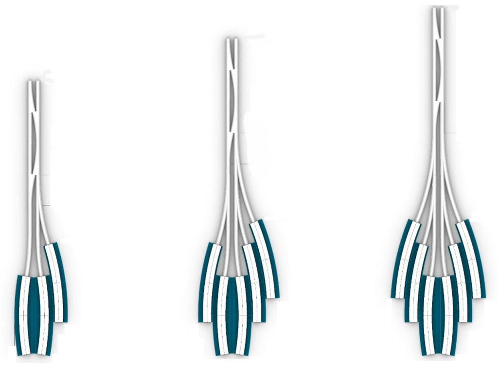
Switch technology
The switch system works using the guidance system and the guideway system and operates entirely without moving components.
When the vehicle approaches a switch, the guidance system locks into either the left or right guidance track. In the switch the guideway simply widens, and the tracks diverge. As a result, the vehicle is pulled either left of right to follow the desired path. After the switch is made, the switch guideway simply splits into two linear guideways, allowing each vehicle to continue its journey.
Characteristic | Performance |
Max. switching speed | 700 kph |
Max. jerk | 0.2 g/s |
Performance by speed [kph] | 100 | 200 | 300 | 400 | 500 | 600 | 700 |
Switch box length [m] | 60 | 120 | 180 | 220 | 280 | 340 | 400 |
3.7 Banking System
CORE FUNCTION - Limit the lateral forces experienced by the payload whilst cornering at high-speed.
The banking system is crucial to achieve small turning radii. A small turning radius is important for spatial implementation of the hyperloop.
The turning radius is limited by the lateral forces that passengers experience whilst taking a turn. The banking system keeps these lateral forces within acceptable range by banking the vehicle at an angle. Consequently, the same speed can be achieved at far smaller turning radii.
The banking angle is achieved in two ways:
- Guideway cant is the fixed angle of the tracks relative to the horizontal axis. This cant angle is simply achieved by installing the tracks at an angle in the guideway.
- Vehicle tilt creates a variable angle between the cabin and the track.
Characteristic | Performance |
Banking angle | 19° (depending on tilting technology, between 13° and 26°) |
Guideway cant | 13° |
Vehicle tilt | 6° (depending on tilting technology, between 0° and 13°) |
Max. lateral acceleration | 0.15 g |
Max. vertical acceleration | 1.12 g |
Performance by speed [kph] | 100 | 200 | 300 | 400 | 500 | 600 | 700 | 1000 |
Curvature (turning radius) [m] | 200 | 626 | 1,407 | 2,502 | 3,910 | 5,630 | 7,663 | 15,325 |
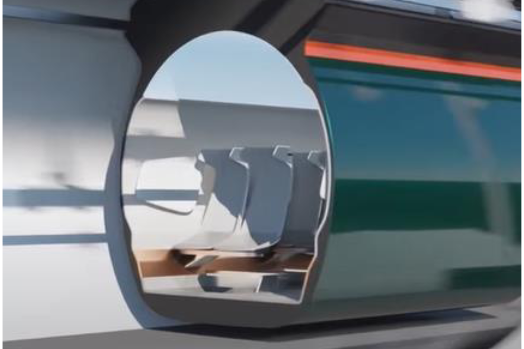
4. Vehicle System
CORE FUNCTION - Move and position the vehicle within the guideway system during nominal operations.
Subsystems and functions – Level 2
- Structural Body System protects the payload from the outside environment and provide a structural body for other connected systems.
- Secondary Suspension System removes unwanted vibrations and disturbances from the levitation
- Environmental Control System ensures the environment is ideal for the payload (e.g., pressure, temperature, humidity, etc.)
- Cooling System to regulate the temperature of systems inside of the vehicle.
Characteristic | Performance |
Length | 24 m |
Outside diameter | 2.5 m |
Seating | 40 seats |
Doors per cabin | 6 doors (incl. 2 emergency exits at the nose and tail) |
(Dis-)embarking time | 2 min |
total drag at cruise (700 kph) | 3100 N (Magnetic = 1650 N ; Aerodynamic = 1450 N) |
Vehicle mass breakdown
Note that the mass breakdown considers the vehicle product and therefore encompasses elements from a variety of systems
Total weight | 25,000 kg |
Payload - subtotal | 8,600 kg (incl. cabin) |
Main body - subtotal | 3,200 kg |
Monocoque | 1,100 kg (1 x 1,100 kg) |
Bogies | 2,100 kg (7 x 300 kg) |
Tractive system - subtotal | 10,000 kg |
Levitation | 3,400 kg (42 x 80 kg) |
Propulsion | 1,700 kg (28 x 60 kg) |
Guidance | 1,700 kg (42 x 40 kg) |
Emergency breaking | 3,200 kg (26 x 120 kg) |
Battery - subtotal | 3,200 kg |
4.1 Vehicle Mechanical System
CORE FUNCTION:
- Protect the payload from the outside environment and provide a structural body for other connected systems.
- Remove unwanted vibrations and disturbances from the levitation system.
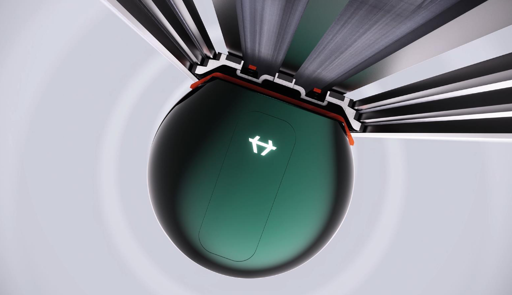
Structural body
The main structural body for the vehicle is a carbon fiber monocoque. This single structure is lightweight and provides the necessary structural strength to the vehicle. Together with the doors, the monocoque provides a pressurized environment to the payload.
Bogies
Onto the monocoque, several aluminum bogies are connected. These bogies provide the structural connection between the monocoque and the tractive systems.
Secondary suspension
The secondary suspension ensures a smooth ride to the passengers and cargo, by filtering out any unwanted vibrations from the levitation system. This is done passively using spring and damper elements that connect the bogies to the structural body.
Characteristic | Performance |
Total structural weight | 3,200 kg |
Monocoque material | Carbon filter |
Bogies material | Aluminium |
4.2 Vehicle Support Systems
CORE FUNCTION:
- Ensure the environment is ideal for the payload.
- To regulate the temperature of the vehicle’s systems.
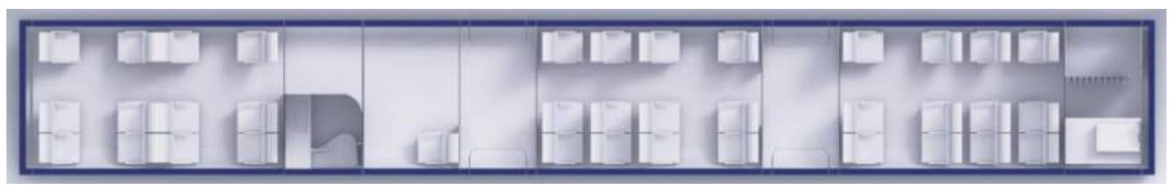
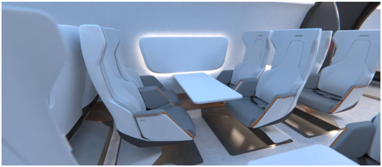
Cabin
The cabin holds all the necessary facilities for passengers to have a comfortable ride. These services include comfortable seating with space for carry on luggage and lavatory facilities. Passengers are kept up-to-date with the latest journey information through interactive screens. A Skylight is used to gave passengers a sense of space throughout the journey.
Environmental Control System
The Environmental Control System (ECS) maintains the safety and comfort of the passengers and cargo. It does so by controlling the cabin air pressure, temperature and humidity. The ECS also regulates the flow of air in the cabin and removes contaminants to ensure satisfying air quality.
Cooling
The cooling systems avoids overheating of the tractive subsystems. Avoiding overheating is important to maintain the efficiency and safety of the tractive systems.
Characteristic | Performance |
Total weight | Approx. 9,000 kg (incl. max payload) |
Cabin length | 20 m |
Cabin width | 2.4 m |
Seats per vehicle | 40 seats |
Number of doors | 6 doors (incl. 2 emergency doors at the nose and tail) |
Door dimensions | 2.2 m (h) x 1.42 m (w) |
(dis-)Embarking time | 2 min |
Legroom | 1 m |
5. Operational Control System
CORE FUNCTION: To schedule and control the vehicle, guideway and hubs within the system.
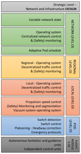
The operational control of the hyperloop system is broken-up into several levels. Each level fulfills a specific set of responsibilities.
- At the Network level pods are scheduled adaptively to optimize demand satisfaction throughout the network. Here traffic control is centralized to control the network flows and monitor safety.
- At the Regional level traffic is controlled decentralized to optimize flow through the main corridors.
- At the Local level traffic is controlled decentralized. Here the departure of pods from stations, the acceleration along on- and off-ramps and pod speeds on the main line are controlled. Also, the vacuum system and segmentation doors are controlled here.
- At the Pod level switching, platooning, headway corrections and emergency protocols are controlled.
- At the Flight module level, each individual guidance and levitation magnet is controlled autonomously.
Performance by speed [kph] | 100 | 200 | 300 | 400 | 500 | 700 | 1000 |
Capacity* [pax/h/dir] | 52,600 | 32,200 | 27,000 | 18,000 | 15,000 | 11,000 | 8,000 |
Headway [s] | 2.7 | 4.5 | 6.2 | 7.9 | 9.7 | 13.2 | 18.4 |
*potentially multipliable with platooning
6. Electrical Infrastructure System
CORE FUNCTION: Supply the system with power and provide a communication network.
Subsystems and functions – Level 2
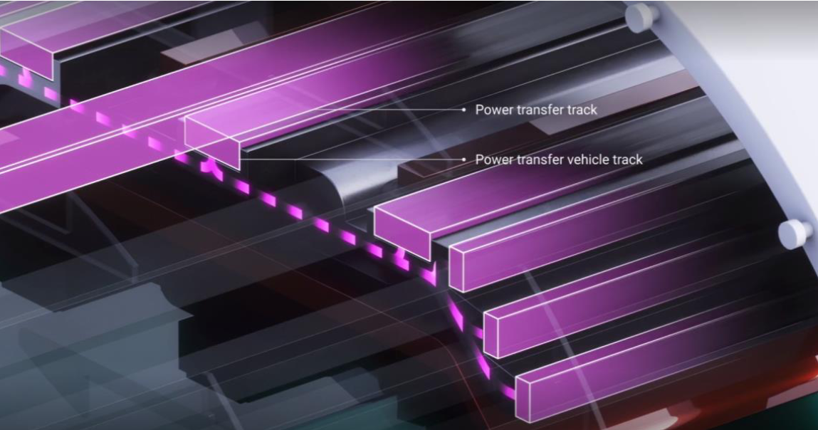
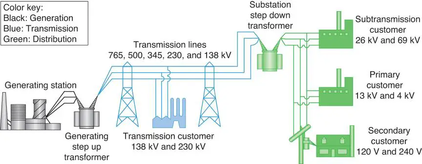
Power Infrastructure System supplies the system with power. The system is supplied with power through two main processes:
- Power transformation occurs using power electronics at a power substation. Here the high-voltage received from the grid is transformed into a medium voltage that can be used by the IPT stations.
- Power distribution then distributes the medium voltage cables along the guideway to supply the IPT stations.
Communication Infrastructure System provides a communication network to the system.
- Between the operational control and the guideway communications are provided through fiber optics backhaul with redundant network.
- Between the guideway and the vehicle communications are provided through a distributed antenna network.
Characteristic | Performance |
Substation intermediate distance | 50 km |
Substation power electronics | ~380 kV to 52 kV |
Medium voltage powerlines | 52 kV |

7. Maintenance System
CORE FUNCTION: To ensure the systems integrity and ability to meet operability standards.
Subsystems and functions – Level 2
- Vehicle Maintenance System ensures the vehicle meets operability standards by preserving the condition of its tractive systems, the vehicle power and electronics, it’s mechanical systems and the support systems.
- Guideway Maintenance System ensures the guideway system meets operability standards by preserving the condition of the structural enclosure, low pressure system, guideway connections and the tracks.
- Hub Maintenance System ensures the hubs meet operability standards by preserving the condition of the passenger hubs, cargo hubs and the depots.
Maintenance Concept
The maintenance design concept aims to maximize the system’s availability, safety and performance whilst minimizing the time and cost of maintenance. This objective is pursued through several key design principles:
- Minimize mechanical friction to minimize wear and tear.
- Minimize moving components to reduce the system’s complexity and potential for system failures.
- Isolated internal environment to protect the system from external influences that can cause a system failure.
Maintenance procedures
The maintenance of the systems occurs through monitoring, functional check-ups and repairs in case of damages that might harm the system’s availability, safety or performance. Monitoring occurs primarily by using the vehicle’s sensors, which are complemented by guideway sensors. These sensors constantly report on the systems performance and status. This information is used by predictive data-analytics to predict when the system might be in need for maintenance.
The impact of maintenance on the systems availability is minimized by making maintenance as fast and simple as possible. For example:
- Modular guideway segments ease the replacement of guideway segments.
- Re-alignment of guideway segments occurs through simple alignment system positioned between the substructure and the guideway.
- Segmentation of guideway segments during maintenance reduce de-pressurization time.
- Schedule maintenance outside of operating hours to avoid impact on system availability.
8. Hub System
CORE FUNCTION: Process, (un-)load cargo and vehicles, or (dis-)embark passengers after arrival at a hub.
Subsystems and functions – Level 2
- Cargo Hub System provides a building where, upon arrival at the Hub, cargo is processed prior, during and post to loading and unloading from vehicles in the low-pressure guideway.
- Passenger Station System provides a building where, upon arrival at the Station, the passenger journey is facilitated prior, during and post to embarking and disembarking from vehicles in the low-pressure guideway.
- Depot System provides a building for the storage and maintenance of vehicles that allows vehicles to move in and out of the low-pressure guideway.
Characteristic | Performance | ||
Passenger Hub | Cargo Hub | Depot Hub | |
Amount of airlocks | 4 | 1 | 1 |
Total turn-around time | 4 min | 6 min | n/a |
Arrival process | 1 min | 1 min | 1 min |
(Dis-)embarking / (Un-)loading | 2 min | 4 min | 4 min |
Departure process | 1 min | 1 min | 1 min |
Capacity per platform | 15 veh/h | 10 veh/h | 10 veh/h |
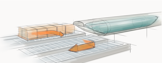
8.1 Airdock
CORE FUNCTION: Provide passengers with access to and from the vehicle in the low-pressure environment.
The airdock carries the benefit of limiting the amount of air that leaks into the guideway. Hereby less power is consumed by the vacuum pumps in order to maintain the low-pressure environment.
In addition, the airdock allows the vehicle to remain in the low-pressure environment, which benefits the material integrity of the vehicle. Since the vehicle goes through less pressure cycles, the material fatigue is limited.
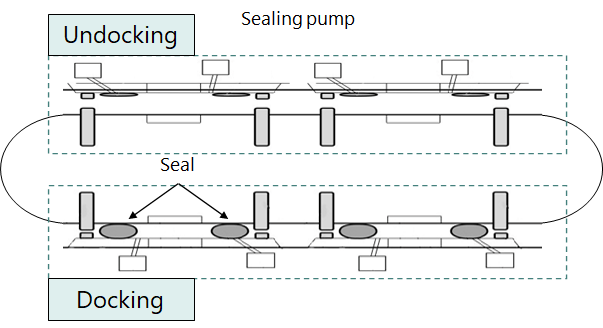
Airdocking process
- Vehicle connects to the platform.
- The seal is made.
- The passage is pressurized through the valve.
- The doors are opened.
- Passenger (dis-)embark the vehicle.
- Doors are closed.
- The passage is depressurized through the pumps.
- The seal is removed.
- Vehicle disconnects from platform.
Characteristic | Performance |
Airlock per vehicle platform | 4 |
Leak rate per cycle | 1.2 m³ (0.3 m³ per airlock) |
Docking | Approx. 45 s |
Undocking | Approx 30 s |
Acknowledgements