
Introduction
The purpose of this paper is to provide the broader public with an informative overview of the hyperloop concept, as envisioned by Hardt Hyperloop. It presents a general description of Hardt’s vision for the hyperloop, complemented by visuals. Additionally, the paper offers insights into the physical progress that Hardt has made in bringing their vision to reality.
Disclaimer
This document describes the vision of the hyperloop as proposed by Hardt Hyperloop at the time of writing. As hyperloop technology is still under development, the design choices presented here are preliminary and subject to change.
August 2023
Executive Summary
What is the hyperloop
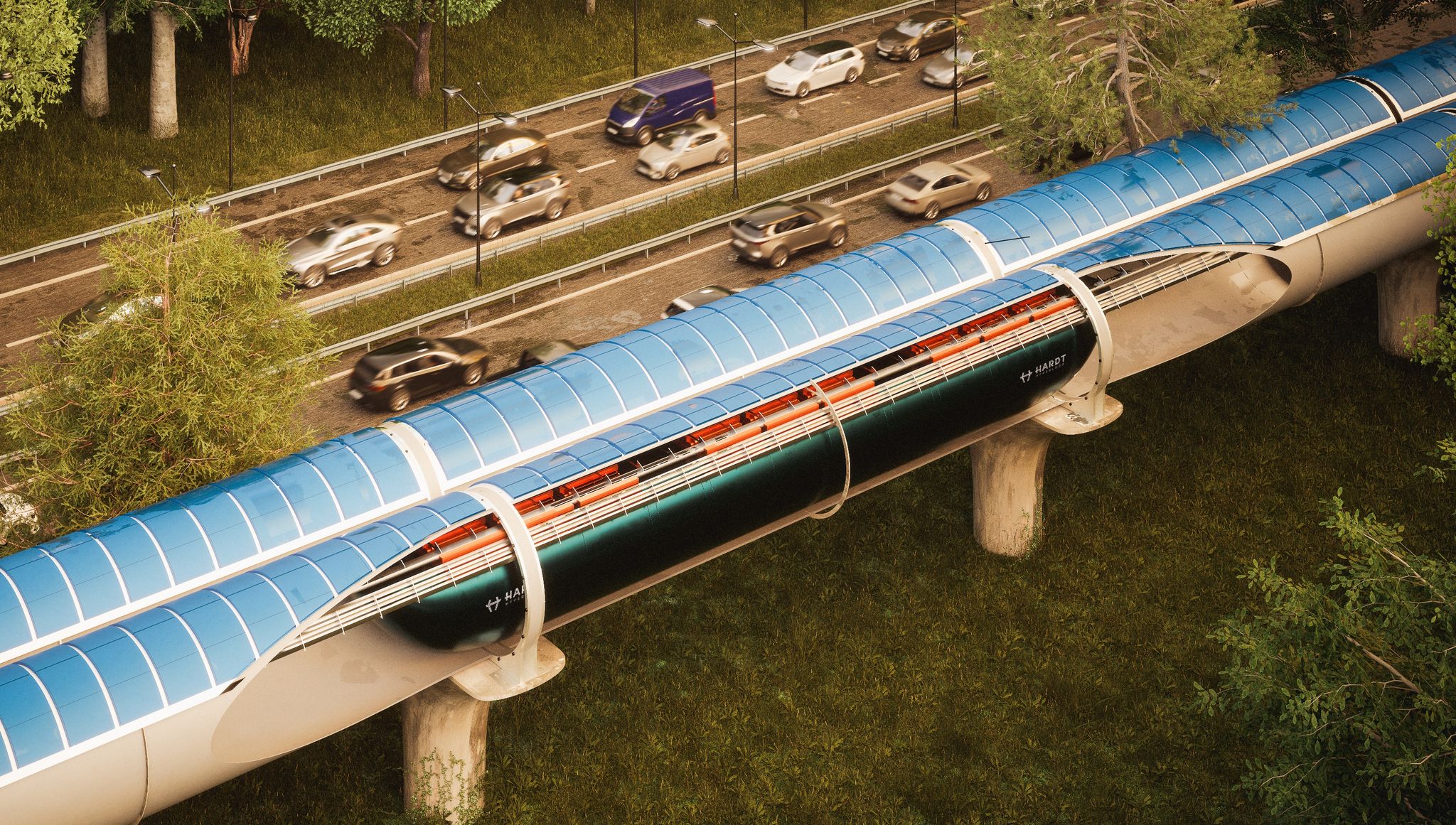
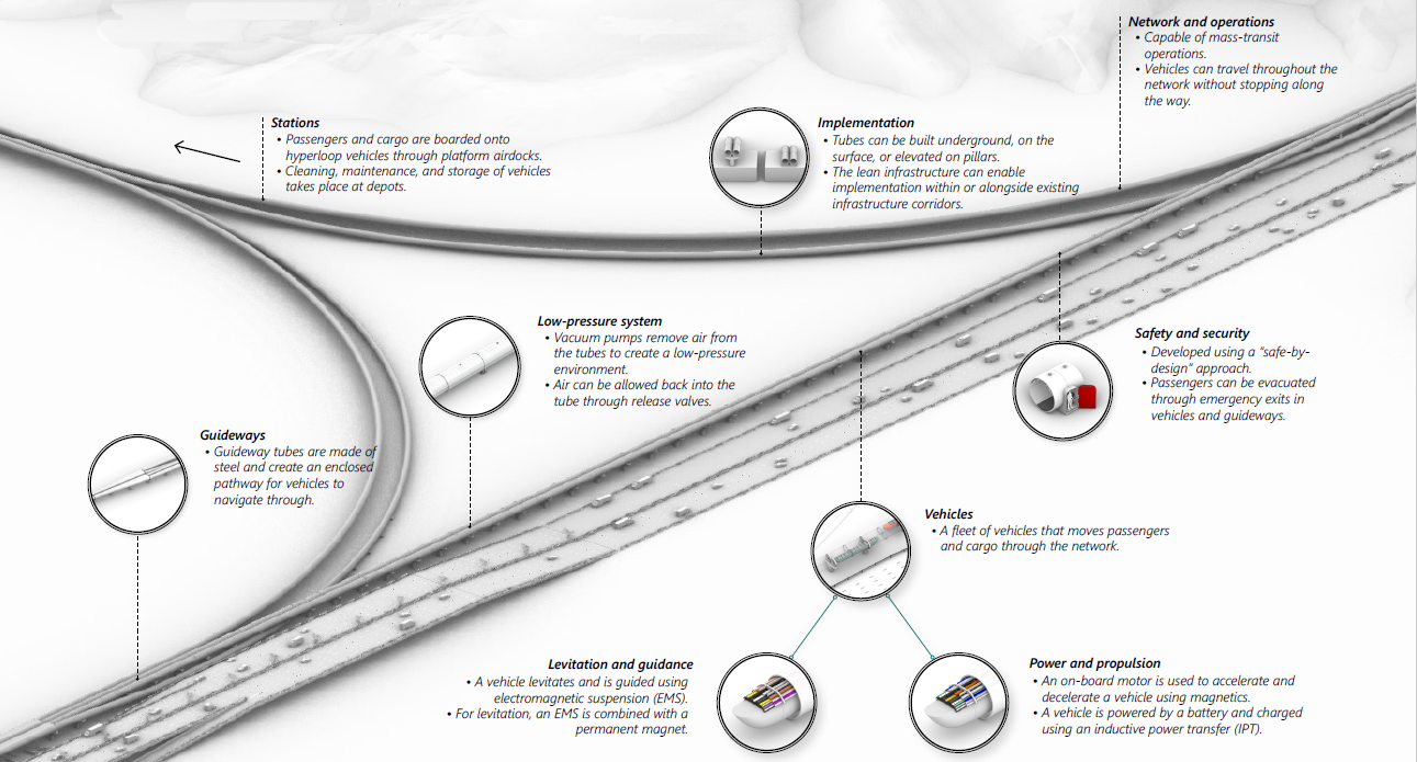
The hyperloop is a sustainable, high-speed transport system for passengers and cargo, operating at mass-transit capacity. Hyperloop’s main components are the vehicles, infrastructure and control system. It employs magnetically guided, driverless vehicles within low-pressure tubes to eliminate physical friction and reduce air resistance. This allows the hyperloop to achieve speeds up to 700 km/h with minimal energy consumption whilst being protected from external influences. Moreover, it operates silently, without vibration or pollution, and requires minimal land use.
Vehicle
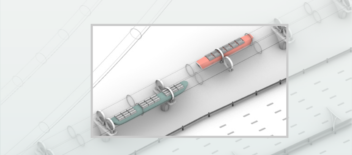
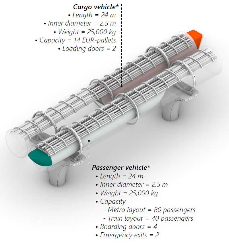
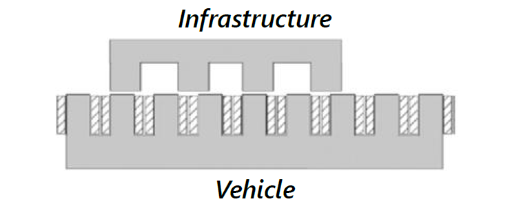
The hyperloop network utilizes pressurized vehicles resembling regional jets for the efficient transport of passengers and cargo. These vehicles have a standardized cross-section and can accommodate passengers or cargo pallets in a range of possible configurations. With a maximum length of 24 meters, the vehicle size is optimized for infrastructure turning radii. Adherence to a common standard guarantees smooth and comfortable rides with acceptable levels of acceleration and vibration. While vehicle sizes and layouts are flexible, all vehicles maintain a standardized interface with the guideway for interoperability across the network. Equipped with active magnetic guidance technology, the vehicles ensure precise tracking and are purposefully designed to be lightweight, resulting in energy-efficient operations.
Magnetic guidance
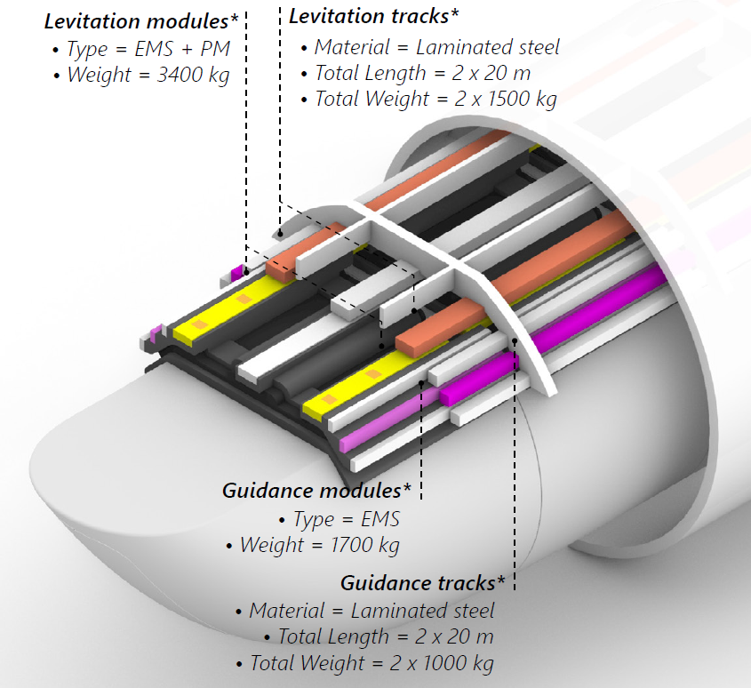
In the hyperloop system, vehicles use contactless magnetic technology to travel through low-pressure tubes. Magnets on the vehicles attract toward passive steel tracks in the tubes for levitation, guidance, propulsion, and braking. Electro Magnetic Suspension (EMS) achieves levitation and guidance through electromagnets, while permanent magnets provide most of the levitating force, ensuring stable levitation with minimal energy consumption. Electromagnets engage with steel teeth in the tracks for propulsion and braking, controlling the vehicle’s speed. The use of magnetic technology eliminates infrastructure wear, reduces the need for strict tolerances, and enhances passenger comfort.
Power
The hyperloop vehicle operates using electric power from an on-board battery. Contactless battery charging occurs using Inductive Power Transfer (IPT) technology along specific sections of the guideway, even during high-speed travel. Regenerative braking allows energy to be recovered and used to recharge the battery. This combination of IPT charging and regenerative braking minimizes energy losses, reducing the required battery capacity and ensuring the vehicle remains charged and ready for operation.
Guideway and implementation
The hyperloop tubes, made of steel, provide a secure, low-pressure environment for vehicle operation. By utilizing vacuum pumps to remove air from the tubes, air resistance is significantly reduced. The tubes can be installed underground, at ground level, or elevated on pillars. The streamlined infrastructure allows for implementation alongside existing infrastructure, using banked turns to maintain high speeds on curved sections of the route. Hyperloop construction costs are estimated to be comparable to those of high-speed rail projects.
Network and operations
Hyperloop networks can offer passenger and cargo capacity for local, regional, national, and continental travel. The network can be operated as a point-to-point service, or as an all-stops service, similar to a metro. Point-to-point services are made possible through the utilization of lane switches without moving components, enabling direct connections between origins and destinations. Vehicles can enter or exit a mainline at high speeds, ensuring a continuous flow with reduced deceleration requirements. This design transforms a network into a highway-like system, enabling direct travel between any two points within the network without the need for intermediate stopping patterns.
Digital foundation
Hyperloop’s digital foundation enhances efficiency and reliability compared to traditional transport. It enables advanced control systems, effective environmental monitoring, and improved passenger safety.
Safety and security
Hyperloop follows a “safe-by-design” approach, prioritizing safety at every step of its development. Its isolated environment, redundancy, and minimal reliance on moving parts contribute to its ability to meet safety requirements. Monitoring and appropriate safety measures are implemented to prevent system failures. In the event of a failure, a section of the tube can be re-pressurized, and passengers can safely evacuate through emergency exits located at the vehicle’s nose, tail, and along the guideway.
Stations
Passengers and cargo access the hyperloop system through stations featuring airdocks with sealed doors for loading and boarding. The vehicle remains within the low-pressure environment during operations. Dedicated depots are utilized for vehicle cleaning, maintenance, and storage, where vehicles can be extracted from the guideway using airlocks.
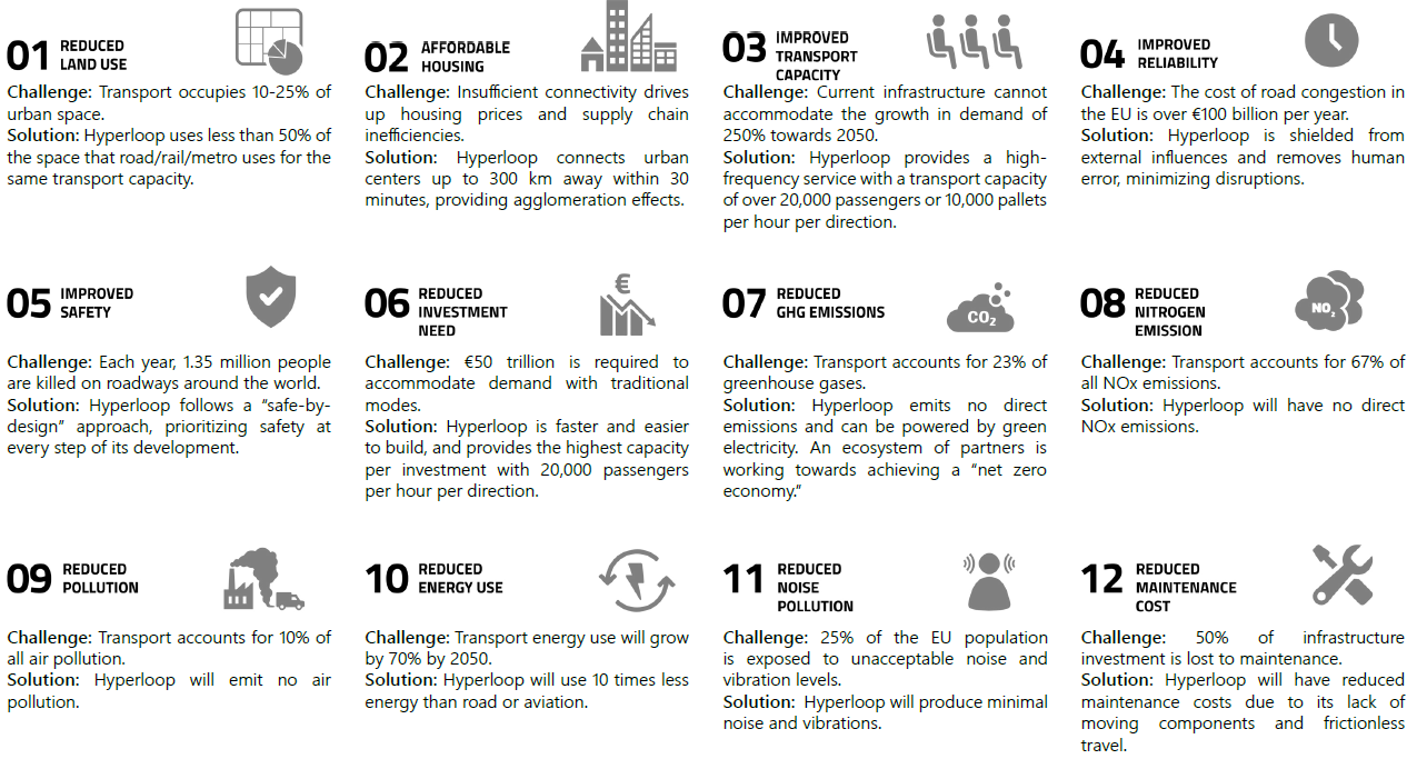
Benefit of hyperloop
System Overview
Vehicles

Vehicles are used to move passengers and cargo throughout the hyperloop network. These pressurized vehicles incorporate a suspension system that ensures a comfortable ride for the payload. The vehicle size is constrained by the infrastructure’s turning radii. While there is flexibility in vehicle size and layout, a standardized interface between the vehicle and guideway is adopted to preserve interoperability across the entire network.
Structure
The vehicle structure is engineered to achieve a balance between strength and lightness, prioritizing safety whilst ensuring energy efficiency. It features a single carbon fiber structure, known as a monocoque, which forms both the vehicle’s structural body and the pressurized enclosure for the payload. Additionally, the monocoque is fitted with aluminum structures called bogies, which house the modules responsible for power, propulsion, levitation, guidance, and braking.
Passenger cabin
The passenger cabin prioritizes traveler comfort by providing a comfortable journey. The vehicle is equipped with a suspension system to ensure a smooth ride by effectively filtering out vibrations. Regular cleaning and refreshing of the cabin occur at designated stations or depots to maintain a comfortable environment for passengers.
The cabin layout is fully-accessible and can be tailored to meet market demands. For commuter routes and shorter trips, a cost-efficient ‘metro-style’ seating configuration is available. Alternatively, for long-distance journeys catering to business and leisure travelers, a more spacious seating arrangement resembling high-speed trains can be provided, complete with lavatories. If necessary, the cabin can be equipped with a compartment for storing large luggage or small storage compartments beneath the seats for storage of carry-on luggage.
System operations are flexibly tailored to accommodate the specific preferences and needs of passengers. For instance, if a metro-style layout is desired, the vehicle’s jerk and deceleration can be limited, enabling passengers to comfortably stand. Conversely, if higher acceleration and deceleration are required, designated seats equipped with seatbelts ensure passengers safely withstand the forces. Furthermore, a dedicated luggage check-in service can be provided, allowing passengers to have their luggage directly delivered to their destination.
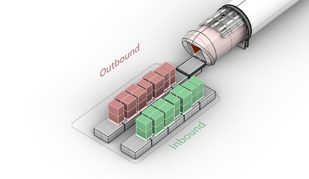
Cargo vehicle
Cargo vehicles can integrate into the hyperloop infrastructure alongside passenger vehicles. Loading and unloading occur through the vehicle’s nose and tail utilizing fully autonomous conveyor belts. These specialized vehicles can move time-sensitive and high-value goods. Large maritime containers are not supported in the hyperloop system, as it is not aligned with the intended market and necessitates a larger tube diameter of six meters.
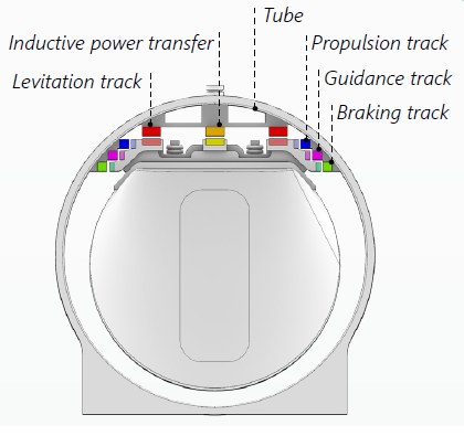
Levitation and guidance

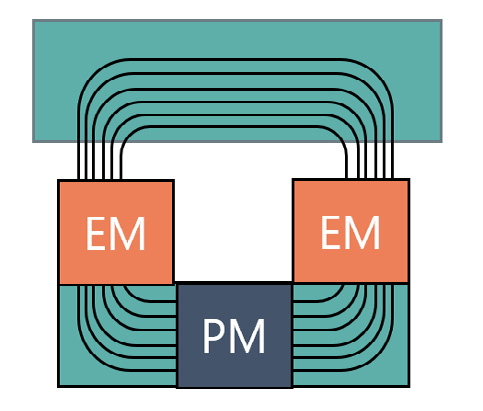
The hyperloop employs an Electro Magnetic Suspension (EMS) system to enable non-contact levitation and guidance of the vehicle. For levitation, the EMS is combined with permanent magnets to improve energy efficiency. This non-contact way of levitation and guidance eliminates wear on the infrastructure, reduces the need for strict infrastructure tolerances, and improves passenger comfort.
A permanent magnet, commonly found on kitchen fridges, is a passive type of magnet that generates a static magnetic field without the need for electricity. It remains magnetized without any external power source.
An electromagnet is an active type of magnet comprising copper coils. When an electric current passes through these coils, it creates a magnetic field.
Electro Magnetic Suspension (EMS)
To achieve levitation and guidance, the hyperloop employs an EMS system. This system operates by utilizing magnetic attraction to a steel track and employs an active control system for stability. The EMS consists of many individual electromagnets that each act as an autonomous system. To ensure redundancy and uninterrupted operation, each electromagnet is powered by multiple vehicle batteries.
Balancing
During levitation, the hyperloop system maintains vertical balance through mechanisms that adjust the magnetic field:
- If the air gap decreases, the magnetic field is decreased, moving the vehicle away from the track.
- If the air gap increases, the magnetic field is increased, drawing the vehicle closer to the track.
For lateral guidance, precise positioning is ensured through magnet forces:
- If the vehicle deviates right, the magnets pull it left.
- If the vehicle deviates left, the magnets pull it right, maintaining the course.
These adjustments occur over 1000 times per second, stabilizing the vehicle without physical contact. Due to the minimal nature of adjustments, the energy consumption of the electromagnets is negligible.
How does the guidance work?
For levitation, the EMS system is combined with a permanent magnet to improve energy efficiency. The permanent magnet generates a static magnetic field that does the heavy lifting of the vehicle and requires no energy. Meanwhile, the electromagnet provides stability and only needs a low amount of power to function.
How does the levitation work?
In terms of guidance, the vehicle incorporates electromagnets positioned along its sides. Just like levitation magnets, each guidance magnet operates autonomously. These magnets keep the vehicle stable and in the middle of the desired path.
Click to see the physical progress in the form of the Propulsion and Levitation Demo (PLD):
 Hyperloop Progress Paper.
Hyperloop Progress Paper.Note:
EMS - Electro Magnetic Suspension
EM - Electro Magnet
PM - Permanent Magnet
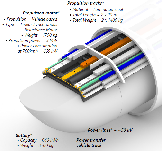
Propulsion and power

The vehicle’s speed is effectively controlled by an on-board Linear Synchronous Reluctance Motor (LSRM), which not only propels the vehicle but also facilitates braking. This motor utilizes the on-board propulsion magnets to generate forward motion and efficiently regenerate energy during braking. The vehicle operates entirely on electric power and is equipped with an on-board battery. This battery can be charged while the vehicle is in operation using a contactless power transfer system that is installed along sections of the guideway.
Propulsion and braking
An electric on-board motor is used to control the speed of the vehicle. The motor can both propel and brake the vehicle using magnetic attraction towards passive steel teeth in the track. The acceleration and deceleration experienced by passengers are comparable to those encountered when traveling on a high-speed train.
Safety and redundancy
Just like the levitation and guidance magnets, the onboard motor incorporates redundancy measures to ensure reliable operation. In the event of a propulsion magnet failure, numerous other propulsion magnets remain operational to maintain the vehicle’s functionality. This redundancy significantly reduces the risk of vehicles becoming stranded and causing network congestion, minimizing potential disruptions to the system operations.
Battery
The vehicle’s electrical systems are powered by an on-board battery. This battery supplies the necessary peak power for vehicle acceleration and has the capability to recapture a substantial portion of the vehicle’s kinetic energy during braking. The ability to recharge the battery from braking energy means that the battery only requires moderate power charging to sustain high-speed cruising. By utilizing an onboard battery, the need for expensive high-power electrical infrastructure, which would significantly increase infrastructure costs, is eliminated.
IPT Charging
The vehicle’s battery is efficiently charged using an Inductive Power Transfer System (IPT), which enables contactless charging. This IPT system is strategically installed along specific sections of the guideway and utilizes induction technology to transfer power to the vehicle. Notably, the IPT system demonstrates high efficiency, capable of charging the vehicle during stationary periods as well as while traveling at high speeds. To optimize the functionality of the IPT system, it will be strategically deployed along high-speed corridors, as well as at platforms, stations, and depots, maximizing its utility throughout the hyperloop network.
Click to see the physical progress in the form of the Propulsion and Levitation Demo (PLD):
Hyperloop Progress Paper.
Hyperloop Progress Paper.Note:
LSRM - Linear Synchronous Reluctance Motor
IPT - Inductive Power Transfer System
Guideway

The guideway is made of steel and provides a secure and low-pressure environment for the vehicles. The vehicles travel along steel tracks using magnets and can switch lanes without any moving parts, even when traveling at high speeds. Proper track alignment is always monitored and maintained to ensure safe operation. Expansion joints are incorporated in the guideway to capture the heat expansion of the tubes, and together with the rubber gaskets maintain the low-pressure environment within the guideway.
Guideway
The guideway consists of steel tubes and tracks, creating a secure and isolated environment for vehicles to travel in. The strength of the steel tubes protects the vehicles from external influences. This prevents delays or dangerous situations that could otherwise be caused by extreme weather conditions, human interference, or wildlife interference.
Switch
Switches play a crucial role in unlocking the full potential of the hyperloop network. They enable vehicles to join the mainline at high speeds without the need for any moving parts.
As a vehicle approaches a switch, the guidance system securely engages with the guidance tracks on either the left or right side of the guideway. Within the switch, the guideway expands, and the tracks diverge, effectively pulling the vehicle toward the desired path. Once the switch is completed, the switch guideway separates into two linear guideways, allowing each vehicle to continue its journey toward its respective destination.
Tracks and alignment
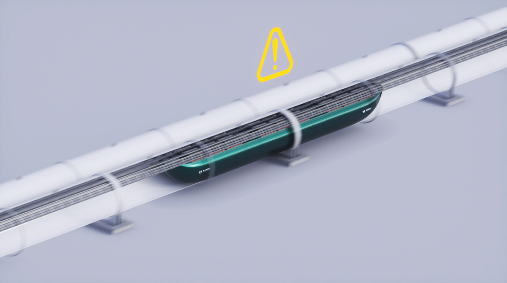
Proper track alignment is crucial when raveling at high speeds of 700 km/h. Over time, soil settlements may lead to guideway displacements, potentially causing track misalignment. Continuous monitoring by the vehicles ensures that any deviations in track alignment are promptly detected. In the event of track misalignment, maintenance procedures are scheduled to re-align the guideway within the required alignment tolerances.
Expansion joints and gaskets
To ensure the structural integrity and preserve the low-pressure environment of the guideway, measures are taken to account for heat expansion and contraction. Given that guideway segments are made of steel, which are subject to thermal fluctuations, the inclusion of expansion joints becomes essential. These joints are positioned every four guideway segments to effectively absorb the heat-induced expansion of the tubes. In addition, the guideway segments are sealed together using large rubber rings, also called gaskets, to prevent air from flowing into the guideway.
Click to see the physical progress in the form of the Infrastructure Prototype (INPR): Hyperloop Progress Paper.
Hyperloop Progress Paper.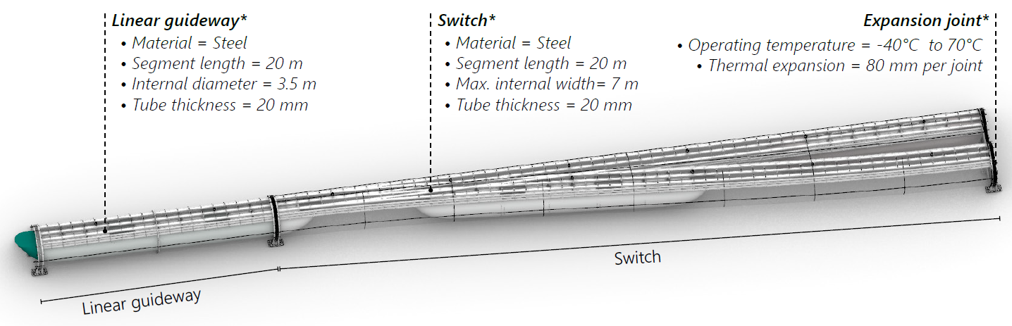
Network and operations

Hyperloop systems allow for passenger and freight vehicles to share the same network. They can be operated as point-to-point services, similar to aviation, or as all-stops services, similar to metro-style operations. All services are operated by a driverless system, capable of accommodating fast and frequent travel. Hyperloop’s services can be scheduled based on a fixed timetable, or they can follow a more flexible timetable, allowing for adaptability in response to unexpected changes in demand.
The hyperloop is designed with integrated digital technology, which distinguishes it from legacy transport modes that often require complex and capital-intensive retrofitting. This digital infrastructure enhances the performance of the overall hyperloop system, enabling more effective control and enhanced monitoring of environmental conditions and passenger safety.
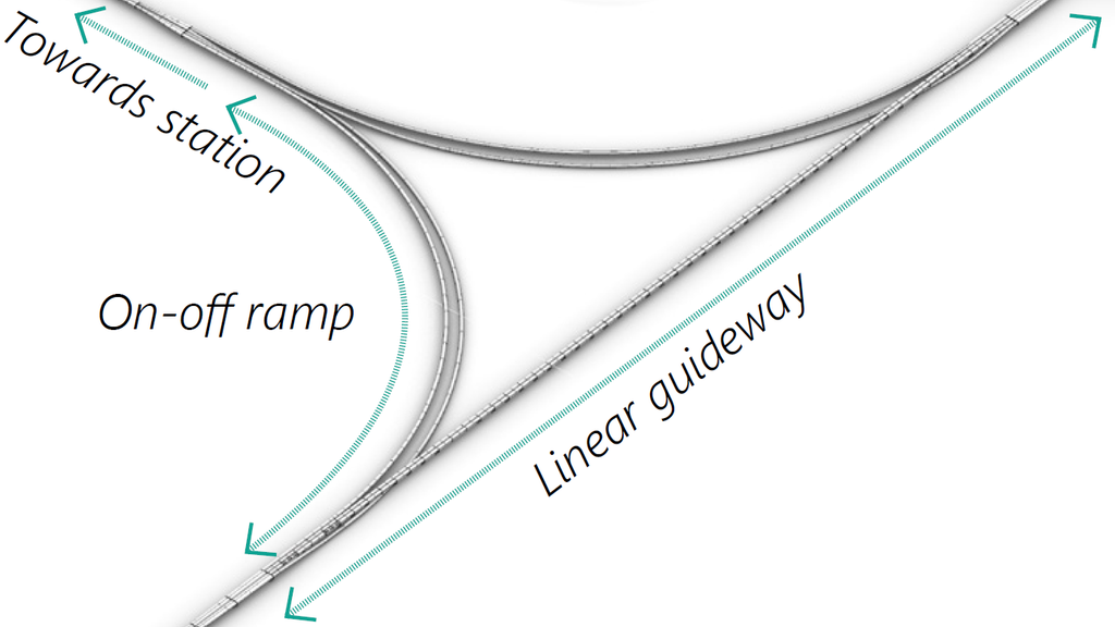
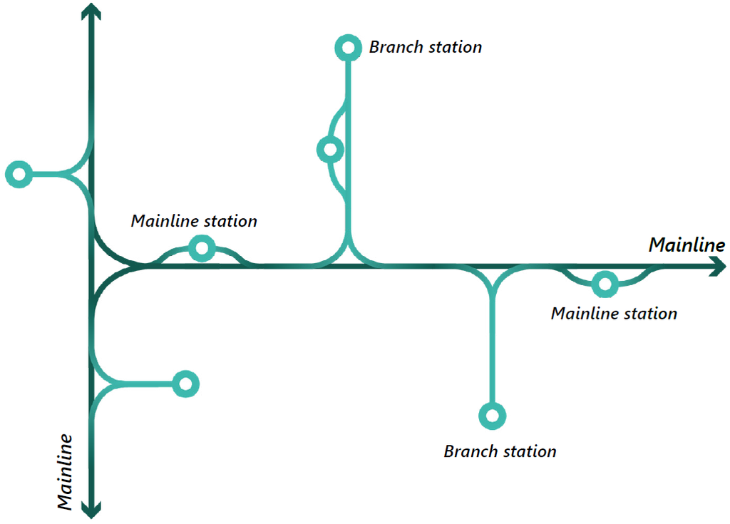
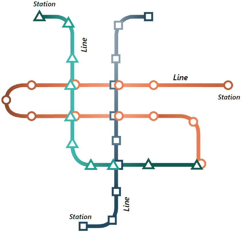
Network
Hyperloop networks can be operated as point-to-point services or all-stops services. Point-to-point services, which are similar to aviation, are designed for high-speed, long-distance trips. These trips would operate like an autonomous highway network, enabling direct connections between origins and destinations without the need for intermediate stops or major slowdowns. Hardt’s innovative switch technology allows for the incorporation of on-and-off ramps and branch lines that connects mainlines to stations. All-stops services, similar to metro-style operations, could serve as an alternative option for local and regional public transport corridors that require fast and frequent services for passengers.
A hyperloop trip
A hyperloop trip begins at a station, where passengers board vehicles at a designated departure platform. The type of trip — point-to-point or all-stops — determines how the trip is conducted. After the trip, passengers disembark from the vehicle at the arrival platform. At all times during operations, a safe distance is maintained between vehicles to prevent the risk of collisions.
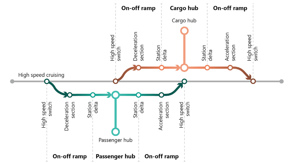
Point-to-point services
During departure, a vehicle starts accelerating and travels to an on-ramp. At a on-ramp, the vehicle gradually increases its speed and safely merges between other vehicles on a mainline. A vehicle transitions from a on-ramp to a mainline through a switch. On a mainline, a vehicle can travel directly toward its destination using speeds of up to 700 km/h. When approaching its destination station, a vehicle moves through another switch to diverge from a mainline onto an off-ramp. Here, the vehicle gradually decelerates while traveling towards its designated arrival platform at a station.
All-stops services
During departure, a vehicle starts to accelerate to its cruising speed (if distances between stations allow for it). Similar to a metro-style service with a fixed stopping pattern, a vehicle will travel directly to the next station. When approaching the next station, a vehicle will gradually decelerate and stop at the next available platform.
Stations and depots

Stations play a vital role in the hyperloop system, facilitating the efficient loading and boarding of passengers and cargo onto vehicles through specially designed airdocks. These airdocks are designed to minimize air leakage into the tubes during boarding and loading operations, whilst vehicles remain in the low-pressure environment. Additionally, the depots serve as important facilities for the cleaning, maintenance, and storage of vehicles.
Airdock
Passengers and cargo embark and disembark from the vehicles utilizing specially designed airdocks. These airdocks serve as a passage between the platform and the vehicles through which payload can enter or exit the vehicle. Upon reaching the platform, the vehicle doors connect with the airdock and create a secure seal. Once the seal is established, the airdock and vehicle doors can be opened, enabling access from the platform to the vehicle. Importantly, the airdock design allows boarding and loading activities to take place while the vehicle remains within the low-pressure environment. This is important for the following reasons:
- The airdock minimizes air leakage into the tube, to reduce the reliance on vacuum pumps and decrease energy consumption to maintain the low-pressure environment.
- The airdock minimizes the number of pressure cycles a vehicle has to endure. Consequently, material fatigue is limited, and the vehicle’s lifespan is significantly increased.
- The airdock minimizes the turnaround time of vehicles and consequently reduces the overall footprint of stations.
Passenger stations
Hyperloop passenger stations are designed to provide a smooth, comfortable, and secure travel experience for passengers. They can be strategically integrated with other transport modes to promote intermodal connectivity.
A hyperloop station can provide the same level of security and ease of travel as experienced when traveling with other modes of high-speed transport. Passengers can check in and board their vehicles quickly and easily, and they will have access to shops and services while they wait for their departure.
Cargo stations
Hyperloop cargo stations are designed to facilitate the loading and unloading of cargo in and out of vehicles. To this end, they provide easy access and good integration with logistical services. The processes of storage, sorting, staging, loading, and unloading are automated as much as possible. Cargo is loaded and unloaded at the cargo dock, where the vehicle remains in a low-pressure environment.
Depot
Depots serve as dedicated facilities for the storage and maintenance of hyperloop vehicles. At the depots, vehicles can be extracted from the low-pressure environment for maintenance and check-ups using an airlock system. Additionally, the depots provide access to the vehicles for cleaning, refreshments, and minor maintenance tasks inside the passenger cabin. Moreover, the depots offer storage capacity to accommodate vehicles that are not in use during non-peak hours.
Safety and security

Hyperloop development adopts a “safe-by-design” approach, prioritizing safety at every step of the development process. The hyperloop’s isolated environment, redundancy, and minimal reliance on moving components helps to improve safety outcomes. For risks that cannot be entirely eliminated in the design, hyperloop will be continuously monitored and use adequate safety measures to prevent system failures. In the rare event of a failure, passengers can safely be evacuated through emergency exits.
Phasing
The hyperloop will be deployed in phases to ensure its safety. The first phase will involve the development of a regulatory framework and the use of a systems engineering approach to identify and mitigate risks. The first routes will be short and will be operated at a higher pressure to ensure passenger safety. During this phase, stewards may be present onboard vehicles to help passengers get acquainted with the new mode of travel. As the technology matures and routes become longer, the operating pressure may be reduced, and the presence of stewards may be phased out.
Safety as a priority
Safety is a top priority in the development of hyperloop. The safety of human life, the protection of the natural environment, the preservation of public and private property, the integrity of the hyperloop infrastructure itself, and the safety of transported goods are all important considerations.
Design principles
To achieve the desired level of safety, several key design principles are consistently applied in the hyperloop design. These principles include:
- Redundancy: The hyperloop system incorporates redundancy, meaning that multiple modules are utilized to perform each function instead of relying on a single component. For instance, multiple levitation modules are employed to ensure the vehicle remains levitating even if one module fails.
- Minimal moving parts: To mitigate the risks associated with component failure, hyperloop minimizes the use of moving parts. This design choice applies to various aspects, including the levitation, guidance, propulsion, and power modules of the vehicle, as well as the guideway and switches. By reducing moving components, the system enhances safety and reliability.
- Isolated environment: Hyperloop operates within an isolated environment, protecting the vehicles from external factors that can compromise safety. This includes adverse weather conditions, human interference, animal encounters, and other disturbances that are known to affect the safety and reliability of other transport modes.
Monitoring
During operations, continuous monitoring of the hyperloop vehicles and guideway is conducted to ensure safe and reliable performance. The vehicles themselves play a key role in this monitoring process as they travel along the guideway. By detecting any changes in the guideway or reporting any deviations in their own state or performance, potential safety hazards can be identified. This proactive approach enables the timely scheduling of maintenance activities to address any issues and prevent any compromise to the safety and integrity of the system.
Security
Hyperloop aims to comply with safety standards that will be determined by future administrators and regulators of the system. Security measures for hyperloop are expected to be similar to those implemented in other transport systems, where similar risks, threats, and vulnerabilities are shared.
In terms of security procedures, passengers may undergo security checks like those conducted at other transport stations for long-distance travel. These checks would allow them to proceed directly to their departure platforms after check-in. Additional security checks may be necessary for cross-border travel, depending on the requirements of the relevant administrators and regulators.
Emergency operations
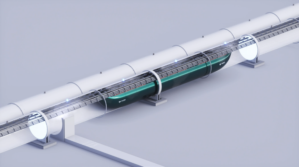
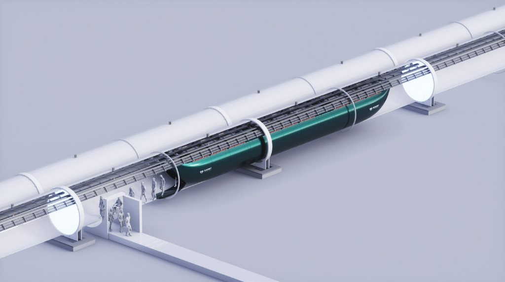
In the event of an emergency in a hyperloop vehicle, protocols are in place to ensure the safe evacuation of passengers. The vehicle will be rerouted to the nearest station, where passengers can safely exit the vehicle. If nearby access to a station is not possible, a well-defined evacuation process will be implemented to evacuate passengers from the vehicle and the guideway.
Guideway evacuation
First, the vehicle is brought to a controlled stop, and a specific section of the tube is sealed off using segmentation doors. Then, the release valves are opened, allowing controlled airflow to pressurize the guideway segment. Passengers can safely exit the vehicle through the designated emergency doors located at the nose and tail of the vehicle. Clear guidance will be provided to passengers directing them to the nearest emergency exit, where they can safely exit the guideway.
It is important to note that in the event of a puncture or leak, the pressure loss within the cabin is gradual, allowing sufficient time to reroute the vehicles to a nearby station or re-pressurize the tube before passengers are exposed to a potentially hazardous low-pressure environment. However, in cases where immediate danger is present, the tube will be promptly re-pressurized to create a safe environment for evacuation from the vehicle.
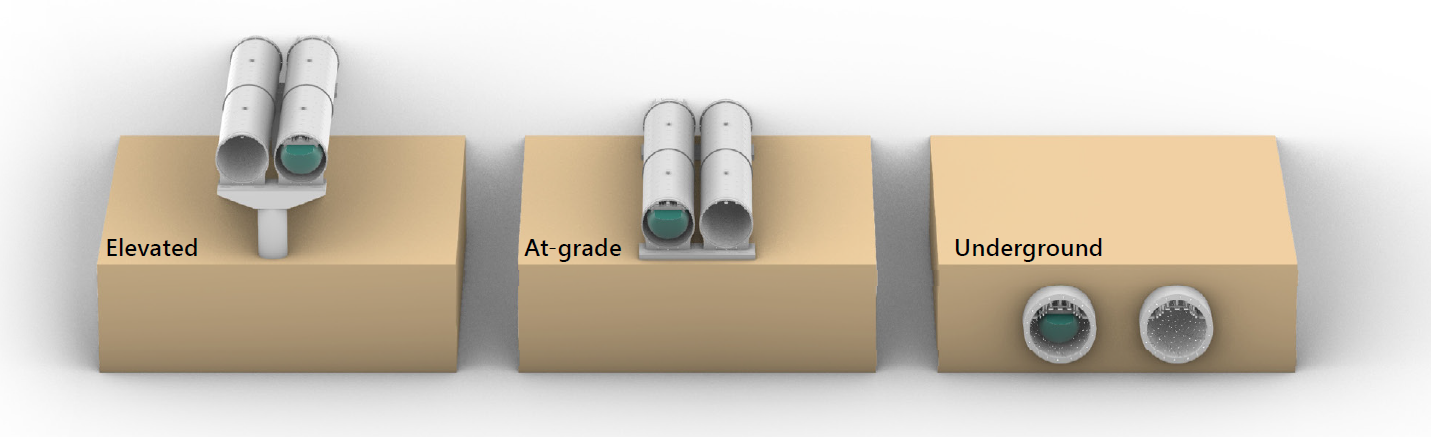
Implementation

The hyperloop system is designed to be versatile, capable of implementation in a variety of scenarios, including above-ground, at-grade, or underground configurations. Each configuration has its own advantages and disadvantages.
Images Low Speed Test Facility (LSTF) and European Hyperloop Center (EHC):
LSTF - Hyperloop Progress Paper
EHC - Hyperloop Progress Paper
Hyperloop Progress Paper
EHC - Hyperloop Progress PaperCorridor types
Above-ground implementation on pillars is a cost-effective approach that minimizes disruptions. It can have a visual impact on the surrounding environment. In urban areas, placing the hyperloop underground helps address visual impacts and space limitations. However, it can be more expensive to build and maintain.
Alignment
The hyperloop’s lean infrastructure and small footprint enable integration with existing infrastructure, making the most efficient use of available space. Moreover, the hyperloop’s flexibility in navigating narrow curves enables it to adapt to existing routes and infrastructure without significant modifications. The specific configuration that is chosen for a particular hyperloop project will depend on a number of factors, including the cost, environmental impact, and existing infrastructure.
Note:
HSR - High speed rail
LSTF - Low Speed Test Facility
EHC - European Hyperloop Center
Cost
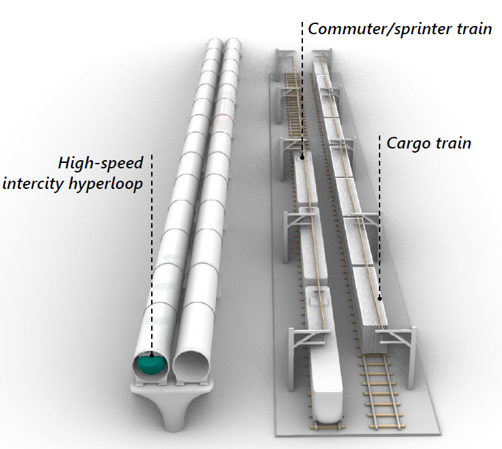
The implementation cost for the hyperloop is comparable to high-speed rail (HSR). Although hyperloop guideway construction may be initially more expensive than HSR, the overall benefits during implementation outweigh the costs. The hyperloop tunnels are only half the size of HSR tunnels, and the inherent strength of steel tubes eliminates the need for expensive bridge constructions for spans up to 20 meters. Consequently, the hyperloop can be integrated with existing roads, railways, and waterways without significant cost escalations.
Curves
The hyperloop’s banking technology is used to navigate sharp turns and align with existing infrastructure. The banking system tilts the vehicle, counteracting lateral forces and ensuring passenger comfort during high-speed curves. This transformation of forces into increased seat pressure maintains passenger comfort throughout the journey. As a result, the hyperloop can maintain high speeds while following existing infrastructure, without compromising passenger comfort.
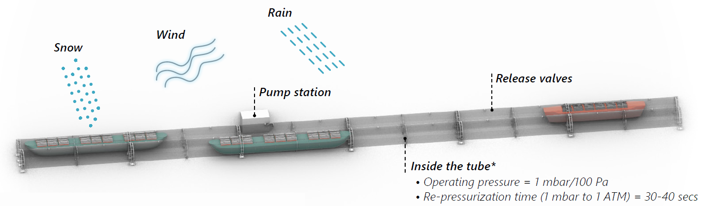
Low-pressure

The hyperloop system utilizes pumps to establish and sustain a controlled low-pressure environment within the tube. These pumps effectively remove any air that may leak into the tube, thereby maintaining the desired low-pressure conditions. Additionally, a re-pressurization system is incorporated to swiftly restore the guideway’s pressure in the event of rapid pressure loss within the vehicle, ensuring the safety of passengers.
Modes of operation
The hyperloop’s low-pressure system operates in three modes: pump down, retention, and re-pressurization. In the pump down mode, the pressure within the guideway is gradually decreased from atmospheric pressure to the desired operating pressure of 1 mbar. During retention, the pressure is maintained at this operating pressure to ensure optimal performance of the hyperloop. Finally, in the re-pressurization mode, the guideway is brought back to atmospheric pressure from the operating pressure.
Guideway leakage
Air leakage in the hyperloop system can originate from connections to the guideway that are not airtight, such as joints and manholes, or from the airdocks used during boarding and loading. Vacuum pumps are employed to counteract air leakage and maintain the desired operating pressure. These pumps work continuously to remove the air that leaks into the system. It is important to note that the power consumption required for maintaining the low-pressure environment is significantly lower compared to the power consumed by the vehicles themselves.
Implementation
The hyperloop vacuum pumps are implemented in the form of pump stations, which are primarily located underground to minimize any potential disruptions to the surrounding area. These pump stations house the necessary equipment required for pump down and retention of the low-pressure environment.
Re-pressurization*
The re-pressurization system in the hyperloop is essential for passenger evacuation and maintenance access. It incorporates valves that allow airflow into the guideway. When re-pressurizing from an operating pressure of 1 mbar, specific pressure thresholds must be reached within defined timeframes. The Armstrong limit of 63 mbar, which is the minimum pressure required for human survival, is achieved within two seconds. Breathing conditions without masks can be provided at 600 mbar in about 15-20 seconds. Finally, reaching atmospheric pressure of 1000 mbar takes approximately 30-40 seconds.
Note:
ATM = Atmospheric pressure
1 mbar = 0.1% ATM
Mode comparison

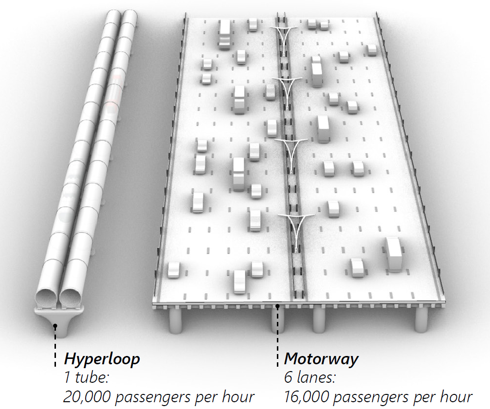
Hyperloop is designed to complement existing modes of sustainable transport. It can alleviate congestion bottlenecks (where other modes are stretched), or facilitate modal shift towards more sustainable modes of travel. Hyperloop leverages urban public transport modes to open up urban space and increase the modal share of public transport. For road and high-speed rail, hyperloop can alleviate bottlenecks created by intercity movements. For aviation, the hyperloop may satisfy the demand for trips that are typically accommodated by short-to-medium haul flights, providing relief to existing airport operations.
Aviation
When realized over longer distances, the hyperloop may satisfy short-to-medium haul aviation demand. This could free up capacity for airports to accommodate long-haul flights, which could increase airport performance without increasing the number of flights. This is important as it could avoid the need for airport expansions and increased flight activity, which cause additional noise and emissions. Electric aviation and sustainable aviation fuels can contribute to improving the sustainability of aviation. However, even when implemented, they will expend 10 times more energy than the hyperloop to transport the same amount of passengers or cargo. The cost and negative externalities of airports and aviation are some of the biggest challenges in transport, and the introduction of hyperloop could help to reduce these challenges.
High-speed rail
Hyperloop can run an intercity service that aggregates cities within a 250 km radius into a single “Daily Urban System”. The ability for hyperloop to allow direct connections at higher speeds enables much shorter travel times between cities compared to rail. The introduction of hyperloop could therefore accommodate part of the travel demand between cities. This could free up capacity on railways for higher frequency services and the movement of freight and marine containers, which cannot be transported by hyperloop.
Road
Even though the adoption of electric vehicles will lower emissions from road transport, hyperloop still consumes significantly less energy to transport the same amount of passengers or cargo, but at much higher speeds. Compared to road transport, hyperloop also has a significantly smaller spatial footprint to move the same amount of passengers or cargo. In addition, by ensuring excellent intermodal connectivity to urban public transport modes, the hyperloop could free up valuable urban and non-urban living space and relieve urban congestion.
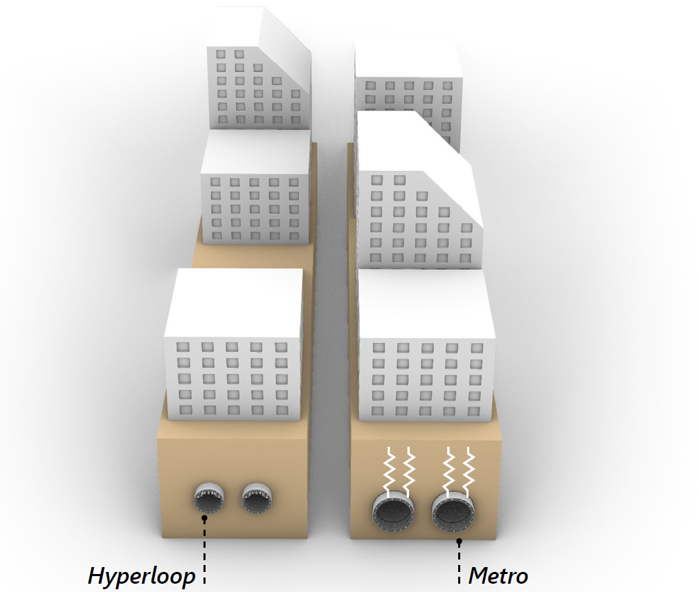
Metro
Hyperloop can be run as a metro-type service with an all-stops service that allows quick on-and-off boarding of passengers at its full seated and standing capacity. This metro-type service can be operated over longer distances at higher speeds and is ideal for trips up to 30 minutes. In this way, it has the potential to reduce travel time and improve the overall modal share of public transport.
In terms of cost, the civil works for an underground metro are a major cost driver. The hyperloop has relatively lower civil costs due to its smaller tunnel diameter and the lack of vibrations. The cost benefits of the reduced civil costs are expected to offset the additional cost required for hyperloop technology.
Physical Progress
The following pages outline the significant milestones achieved by Hardt Hyperloop in the development of hyperloop technology:
- Propulsion and Levitation Demo (PLD)
- Low Speed Test Facility (LSTF)
- Single Magnet Prototypes
- Passenger Cabin
- Infrastructure Prototype (INPR)
- Propulsion Rig
- European Hyperloop Center (EHC)
Hardt Hyperloop development timeline
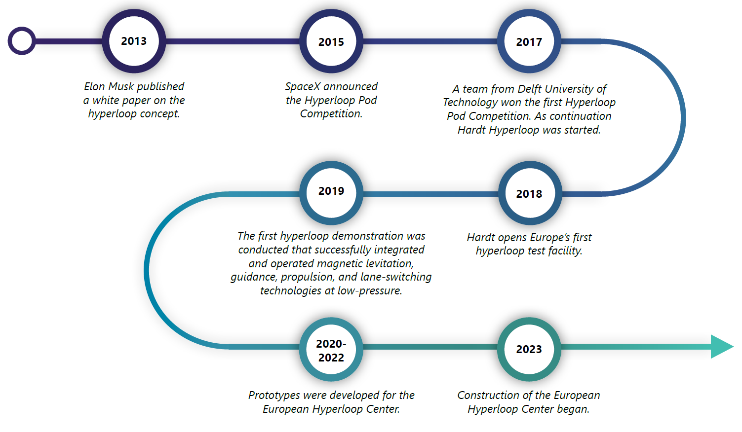
Propulsion and Levitation Demo (PLD)
The Propulsion and Levitation Demo (PLD) stands as a significant achievement in the development of hyperloop technology. Built between 2017 and 2018, the PLD prototype served as a crucial milestone by integrating and testing the levitation, guidance, and propulsion subsystems together for the first time.
The PLD prototype consisted of a 2-meter track and successfully moved a 130 kg vehicle. It employed Electromagnetic Suspension (EMS) combined with a permanent magnet for levitation, while propulsion was accomplished through a track-based Linear Synchronous Motor (LSM).
The successful demonstration of the PLD prototype validated the feasibility of integrating these critical subsystems in a hyperloop system. Achieving a technology readiness level of 3, the PLD served as a proof of concept and laid the foundation for further advancements in hyperloop technology.
Today, the PLD prototype holds a prominent place at Hardt Hyperloop’s experience center, located at their office in Rotterdam. It serves as an educational tool for visitors, showcasing the company’s vision for the future of transport. Currently, Hardt envisions hyperloop propulsion to be vehicle-based instead of track-based.
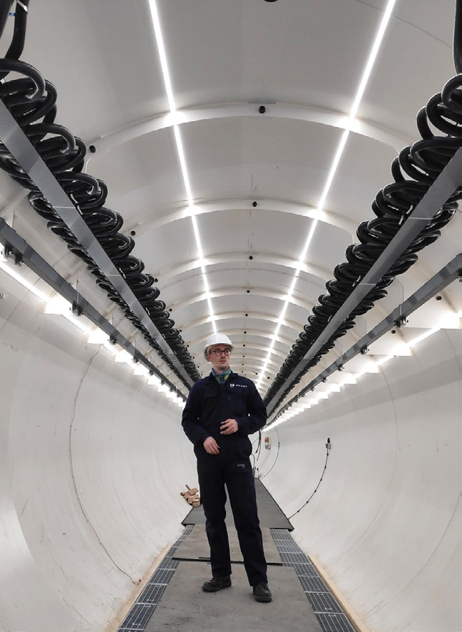
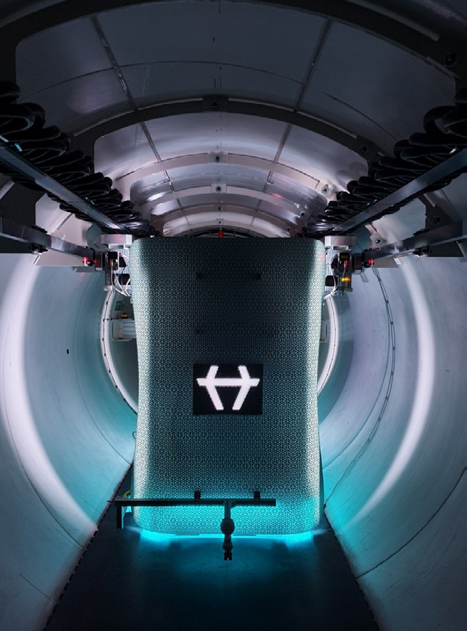
Low Speed Test Facility (LSTF)
The Low-Speed Test Facility (LSTF) served as a major milestone in the development of hyperloop technology. Developed between 2018 and 2019, it was the first real-scale prototype that integrated all the necessary subsystems for hyperloop transport.
Operating in a low-pressure environment, the LSTF demonstrated the successful integration and operation of the levitation, guidance, propulsion, suspension, and switching technologies. The prototype featured a 30-meter-long steel tube with a diameter of 2.7 meters and operated at an atmospheric pressure of 0.1%.
One of the notable achievements of the LSTF was the successful demonstration of Hardt’s switch technology. This innovative technology, devoid of moving components, enables direct connections between origins and destinations that unlocks the full potential of the hyperloop network.
The successful demonstration of the LSTF marked a significant milestone, achieving a technology readiness level of 3 (TRL-3). It served as an experimental proof of concept, showcasing the operational capabilities of the levitation, guidance, and propulsion subsystems at full-scale, paving the way for further development and testing.
Additionally, the LSTF became the world’s first real scale hyperloop test center, representing another significant milestone in the advancement of hyperloop technology. This state-of-the-art facility provides engineers and researchers with the opportunity to conduct real-world testing, gather valuable performance data, and refine the technology to enhance its efficiency and safety. After the LSTF was developed, Hardt has transitioned from a track-based propulsion system to a vehicle-based system.
Back to implementation:
.
Single Magnet Prototypes
The Static Single Magnet Prototype (SSMP) and the Dynamic Single Magnet Prototype (DSMP) were significant milestones in the development of hyperloop technology between 2019 and 2021. These prototypes aimed to accurately measure and control the forces and behavior of the magnets used for levitation and guidance in all directions.
The SSMP was specifically designed to measure the performance of full-scale magnets. It allowed for the installation and positioning of different magnets and tracks, enabling precise measurements of forces and rotations at various positions and current levels. Force sensors were employed to measure forces in all directions, providing valuable data for magnet control.
On the other hand, the DSMP focused on testing the dynamic behavior of levitation magnets and suspension systems. It simulated track disturbances at high speeds, utilizing a vibration table to replicate real-world conditions. The prototype was used to test how much power was necessary to levitate at different distances from the track and how much power had to go through the magnet to maintain stable levitation.
Both prototypes achieved a technology readiness level of 5 (TRL-5) for levitation and guidance. The tests conducted on these prototypes significantly enhanced the understanding of magnet and suspension system performance within a hyperloop system. The data obtained from these tests played a crucial role in refining the technology and advancing its readiness for practical implementation.
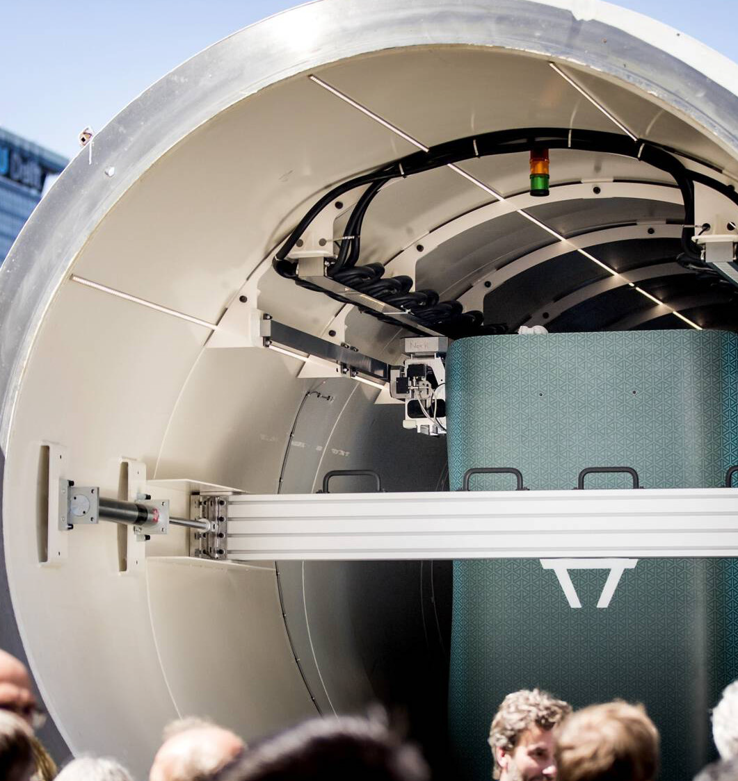
Passenger Cabin
In 2020, Hardt Hyperloop unveiled the CABIN-1, a fully functional model of a hyperloop cabin designed to offer passengers a glimpse into the future of hyperloop travel. Developed in collaboration with industry leaders Recaro, Continental, and Accenture, the CABIN-1 provides an immersive experience of traveling in a hyperloop cabin.
Designed with passenger comfort in mind, the CABIN-1 showcases a spacious interior with a diameter of 2.5 meters. Measuring three meters in length, it offers seating for two passengers, with ample space below the seats for storing carry-on luggage. To enhance the sense of openness, the cabin features a skylight in the roof, providing passengers with a view of the surroundings during their journey.
Keeping passengers informed and engaged, the CABIN-1 is equipped with a display screen that provides real-time journey information. This ensures that passengers stay up to date with the latest updates and travel details throughout their hyperloop experience.
The CABIN-1 serves as a mobile test setup, allowing it to travel around the world and offer people the opportunity to sit inside a future hyperloop cabin.


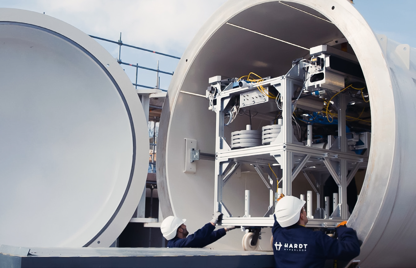
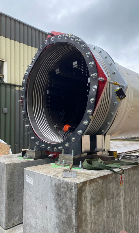
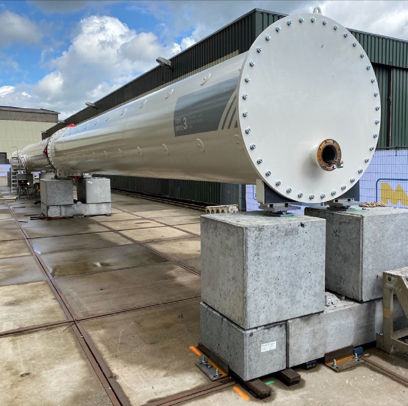
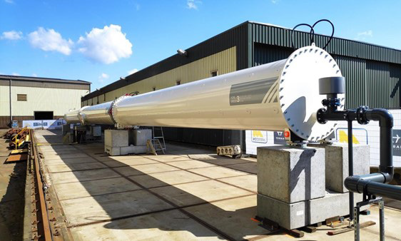
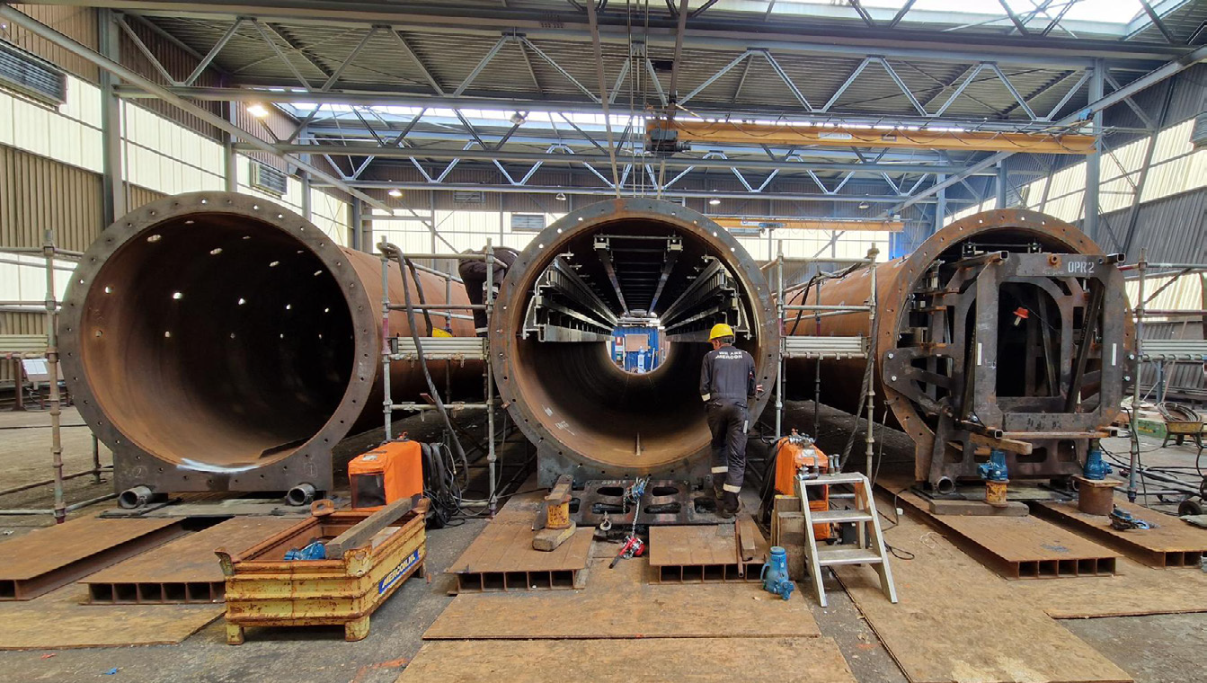
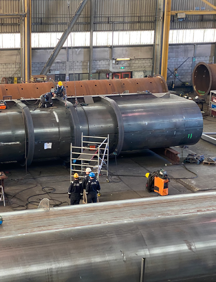
Infrastructure Prototype (INPR)
The Infrastructure Prototype (INPR) played a crucial role in testing the manufacturing and assembly methodology for plug-and-play pipe sections. Its purpose was to ensure the feasibility and efficiency of manufacturing, assembly and construction of hyperloop tube sections for the European Hyperloop Center (EHC) in the Dutch province of Groningen.
The INPR, developed over a span of two years from 2019 to 2021, featured a tube diameter of 1.4 meters and operated at 0.1% atmospheric pressure. It served as a testing ground for various technologies and processes involved in hyperloop infrastructure. One of the key achievements of the prototype was the high-precision installation of tracks within the tubes, ensuring smooth and stable operations.
Additionally, the INPR demonstrated the effectiveness of the low-pressure system, which is essential for maintaining the hyperloop’s desired operating environment. The prototype also showcased the implementation of expansion joints to mitigate thermal expansion and ensure the structural integrity of the system.
Furthermore, the INPR demonstrated the rapid and efficient assembly of the pipe sections in a factory setting, showcasing the scalability and modularity of the hyperloop infrastructure. This successful demonstration led to the attainment of Technological Readiness Level 5 (TRL-5) for infrastructure, validating the readiness of the technology for large-scale implementation.
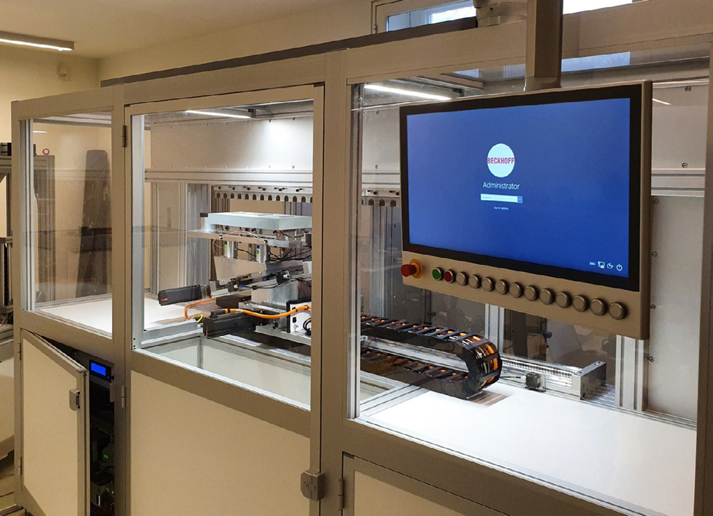
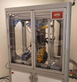
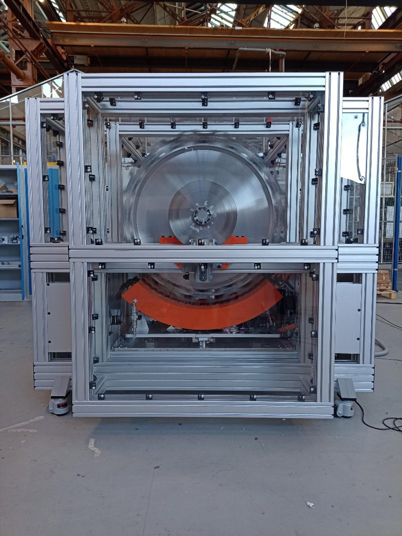
Propulsion Rig
The Propulsion Rig is a vital prototype developed by Hardt in 2022 and 2023 specifically to test the performance of their innovative Linear Synchronous Reluctance Motor (LSRM). This motor represents a new type of propulsion system that will be installed on the hyperloop vehicle used in the European Hyperloop Center (EHC).
The primary objective of the Propulsion Rig is to validate the performance and efficiency of the propulsion magnets required for the motor of the EHC vehicle. The rig itself consists of a 1-meter diameter flywheel that is accelerated by the propulsion magnet positioned beneath it. This setup simulates the track and allows for comprehensive testing of the motor’s performance and control.
Through the Propulsion Rig, testing is conducted at various speeds, with successful trials already reaching speeds of up to 300 kilometers per hour in the first quarter of 2023. The results obtained from these tests have validated the performance of the propulsion magnets, providing crucial insights and data for further improvements to be made in preparation for the EHC vehicle.
Note:
EHC = European Hyperloop Center
LSRM = Linear Synchronous Reluctance Motor
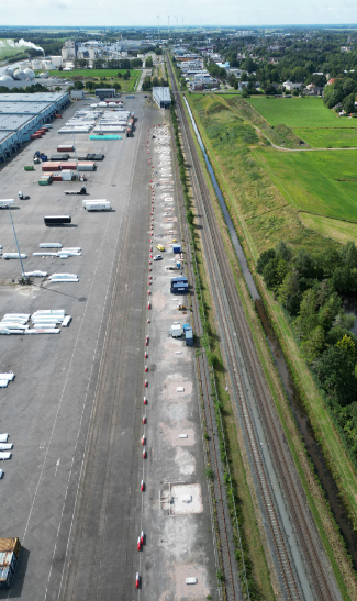
European Hyperloop Center (EHC)
The European Hyperloop Center (EHC) is a state-of-the-art testing facility located in Groningen, the Netherlands. It is currently being constructed as part of the Hyperloop Development Program (HDP), which is a collaborative effort between the Province of Groningen, the City of Groningen, and Hardt Hyperloop.
The primary objective of the EHC is to serve as a hub for testing, validating, and standardizing hyperloop technology. To this end, the EHC is open to any company participating in the HDP program, enabling companies to learn from each other, share best practices, and work towards a common European standard for hyperloop systems. By fostering collaboration and knowledge-sharing among various industry players, the EHC aims to accelerate the development and adoption of hyperloop technology.
Construction of the facility, including the tube and site preparation, is currently underway and is expected to be completed by late 2023. Hardt plans to use the facility in 2024 to validate the following technologies and to advance their technological readiness levels (TRL):
- Tracks: levitation, guidance, and safety (TRL-6)
- Levitation and guidance: at high-speed (TRL-6)
- Propulsion: vehicle-based (TRL-6)
- Magnet control: at high-speed (TRL-6)
- Suspension: at high-speed (TRL-6)
- Tubes: Ø2.5 meter (TRL-6)
- Low pressure system: 0.1% atmospheric pressure (TRL-6)
- Lane switch: at high-speed (TRL-6)
- Wireless communications: at high-speed, Wi-Fi/5G (TRL-6)
- Vehicle and supervisory control: extensive functionality (TRL-6)
- Expansion joints: mitigation of all thermal exposure (TRL-6)
- Rapid assembly: factory assembly (TRL-6)
Back to implementation:
.
For further questions and inquiries please contact us at: connect@hardt.global
Hardt Hyperloop:
Marconistraat 16
3029 AK, Rotterdam
The Netherlands
+31 085 23 897 00
www.hardt.global
