
An overview describing the components of the hyperloop product in terms of its general characteristics and specification
Disclaimer
This document describes the vision of the hyperloop as proposed by Hardt Hyperloop at the time of writing. As hyperloop technology is still under development, the design choices presented here are preliminary and subject to change.
General Hyperloop Characteristics
Characteristic | Performance |
Guideway capacity | 11.000 Pax/h/dir (at 700 kph) (multipliable with platooning) |
Vehicle capacity | 40 Passengers ; 12 Euro Pallets |
Design capacity | 1000 kph max. ; 700 kph cruise |
Operational pressure | 1 mbar |
Operating temperature | -25 °C to 75 °C (can be tailored to location) |
Average energy consumption | 42 Wh/pax-km - determined for a reference route including vacuum energy consumption (70% occupancy, 60% cruising & 40% acc. & dec.) |
Vehicle power consumption | 3.3 MW at max. acceleration ; 665 kW at cruising speed (700 kph) |
Propulsion power | 3 MW |
Levitation airgap | 15 mm |
Vehicle length | 24 m |
Vehicle Internal diameter | 2.5 m |
Tube internal diameter | 3.5 m |
Blockage ratio | 60% |
Guideway material | Steel |
Substructure material | Concrete |
Longitudinal acceleration | 0.11 g or 1.1 m/s² average ; 0.2 g or 2.0 m/s² peak |
Deceleration | Operational braking = 0.15 g or 1.5 m/s²
Emergency braking = 0.8 g or 8 m/s² |
Cant (guideway) | 13° |
Tilt (vehicle) | 6° (technology underdevelopment, expected between 0° and 13°) |
Banking angle | 19° (depending on tilting technology, between 13° and 26°) |
Equivalent angle deficiency | 7.5° (depending on tilting technology, between 0° and 13°) |
(uncompensated) Lateral acceleration | 0.15 g or 1.5 m/s² |
Total corner acceleration | 0.5 g or 5.0 m/s² (made possible by 19° banking with 0.15 g max. lateral acceleration on pax) |
Min. turning radius | 200 m |
Max. Lateral jerk | 0.05 g/s in linear guideway ; 0.2 g/s in switch box |
Max. Longitudinal jerk | 0.1 g/s or 1.0 m/s² |
Max. Gradient | 10% |
Max. Upward acceleration | 0.06 g or 0.6 m/s² |
Max. Downward acceleration | 0.12 g or 1.2 m/s² |
Performance by speed [kph] | 100 | 200 | 300 | 400 | 500 | 600 | 700 | 1000 |
Capacity [pax/h/dir] (x 10,000) | 52.6 | 32.2 | 23.2 | 17.1 | 14.9 | 12.6 | 10.9 | 7.87 |
On ramp length [km] | 0.2 | 0.8 | 1.8 | 3.7 | 6.6 | 9.3 | 12.6 | 25.4 |
Off ramp length [km] | 0.3 | 1.0 | 2.3 | 4.1 | 6.4 | 9.3 | 12.6 | 25.7 |
Curvature (turning radius) [km] | 0.2 | 0.6 | 1.4 | 2.5 | 3.9 | 5.6 | 7.7 | 15.3 |
Guideway connection angle [deg] | 2.72 | 1.83 | 0.81 | 0.46 | 0.29 | 0.20 | 0.15 | 0.07 |
Switch box length [m] | 60 | 120 | 180 | 220 | 280 | 340 | 400 | 560 |
Transition curve length [m] | 83 | 167 | 250 | 333 | 417 | 500 | 583 | 833 |
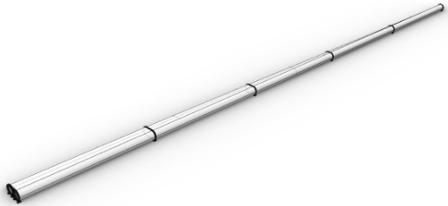
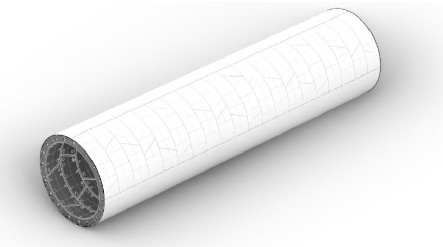
1. Guideway
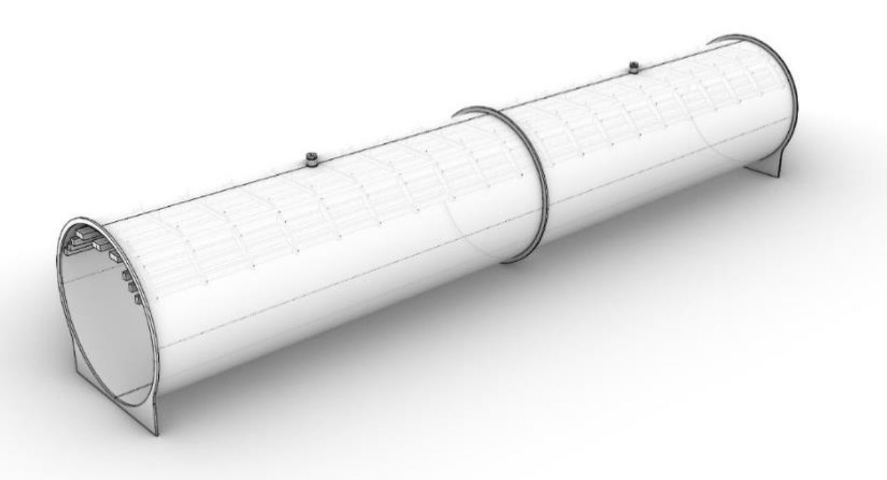
1.1 Linear Guideway
Characteristic | Performance |
Production | Off-site manufacturing and assembly of 20-m segments |
Material | Steel |
Segment length | 20 m (location dependent - landscape) |
Blockage ratio | 60% |
Operating pressure | 1 mbar |
Min. turning radius | 200 m |
Cant (guideway) | 13° |
Max. gradient | 10% |
Max. lateral jerk | 0.2 g/s |
Specification | Value |
Internal tube diameter | 3.5 m |
Length | 20 m |
Pipe thickness | 20 mm |
Flange thickness | 280 mm |
Total weight | 49 t (per 20-m segment) |
Performance by speed [kph] | 100 | 200 | 300 | 400 | 500 | 600 | 700 | 1000 |
Capacity [pax/h/dir] (x 10,000) | 52.6 | 32.2 | 23.2 | 17.1 | 14.9 | 12.6 | 10.9 | 7.87 |
On ramp length [km] | 0.2 | 0.8 | 1.8 | 3.7 | 6.6 | 9.3 | 12.6 | 25.4 |
Off ramp length [km] | 0.3 | 1.0 | 2.3 | 4.1 | 6.4 | 9.3 | 12.6 | 25.7 |
Curvature (turning radius) [km] | 0.2 | 0.6 | 1.4 | 2.5 | 3.9 | 5.6 | 7.7 | 15.3 |
Guideway connection angle [deg] | 2.72 | 1.83 | 0.81 | 0.46 | 0.29 | 0.20 | 0.15 | 0.07 |
Switch box length [m] | 60 | 120 | 180 | 220 | 280 | 340 | 400 | 560 |
Transition curve length [m] | 83 | 167 | 250 | 333 | 417 | 500 | 583 | 833 |
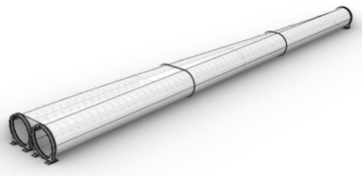
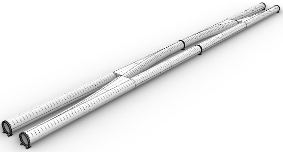
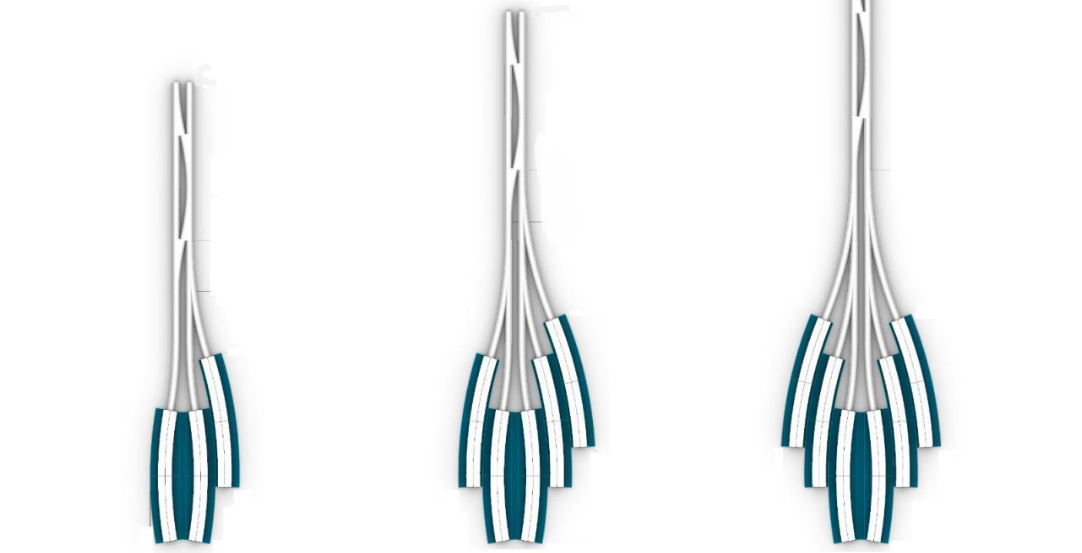
1.2 Switch Guideway
Characteristic | Performance |
Production | Off-site manufacturing and assembly of 20-m segments |
Material | Steel |
Segment length | 20 m |
Blockage ratio | Min. = 25% ; Max. = 60% |
Operation pressure | 1 mbar |
Max. lateral jerk | 0.2 g/s in switch box |
Specification | Value |
Width | Internal: Min. = 3.5 m ; Max. = 7 m |
Height | Internal: 3.5 m |
Pipe thickness | 20 mm |
Flange thickness | 280 mm |
Total weight | ~130 tons (per 20-m segment) |
Performance by speed [kph] | 100 | 200 | 300 | 400 | 500 | 600 | 700 | 1000 |
Pipe segments | 3 | 6 | 9 | 11 | 14 | 17 | 20 | 28 |
Switch box length [m] | 60 | 120 | 180 | 220 | 280 | 340 | 400 | 560 |
1.3 Terminal Switch Guideway
Characteristic | Performance |
Production | Off-site manufacturing and assembly of 20-m segments |
Segment length | 20 m (location dependent - landscape) |
Operating pressure | 1 mbar |
Max lateral jerk | 0.2 g/s in switch box |
Max. speed | 100 km/h |
Specification | Value |
Length | 160 m |
Diameter | Internal: Min. = 3.5. m ; Max. = 7 m |
Height | Internal: 3.5 m |
Pipe thickness | 20 mm |
Flange thickness | 280 mm |
Total weight | 1330 tons |
1.4 Evacuation system
Specification | Value |
Operating pressure | 1 mbar |
Material | Steel |
Interface guideway type | Passenger Hub | Cargo Hub | Depot Hub |
Airdocks [#] | 4 | 1 | 1 (airlock) |
Turnaround time [min] | 4 | 6 | n/a |
Capacity [veh/h] | 15 | 10 | n/a |
Leakage volume [m³/veh] | 1.2 | 0.6 | 80 |
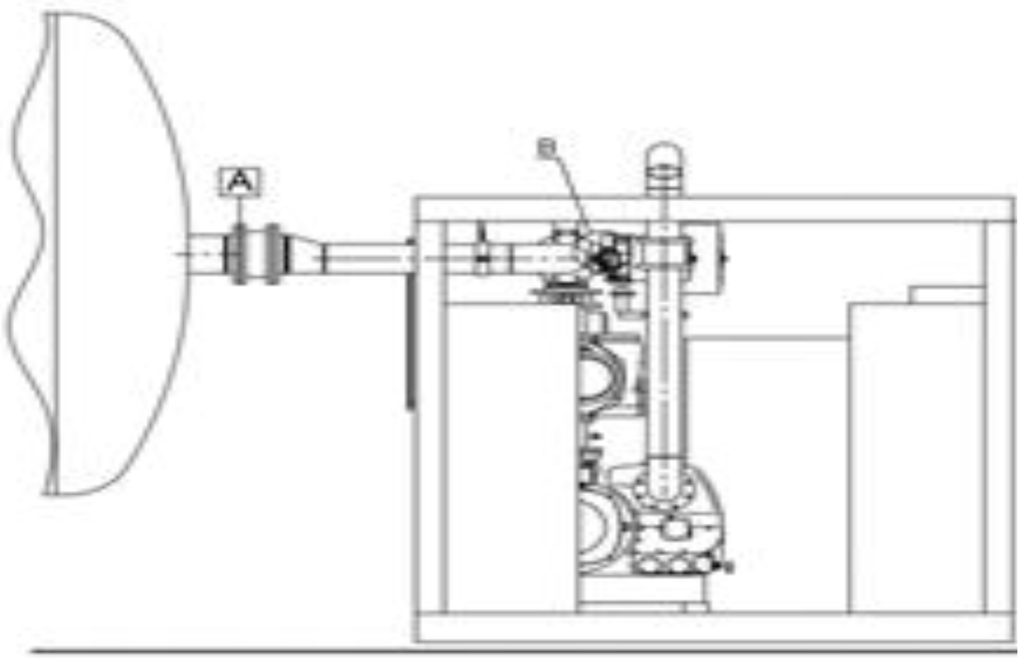
1.4 Guideway Connections
General characteristic | Performance |
Operational temperature | Min. = - 36 °C ; Max. = 73 °C |
Turning angle | 5.73° (required to achieve a 200-m radius with 20-m guideway section) |
Expansion joint | Value |
Material | Steel & Stainless Steel |
Linear exp. joint | 2,875 kg |
Switch exp. joint mass | 4,000 - 6,000 kg |
Length | 550 mm |
Linear exp. joint diameter | Internal = 3.5 m ; External = 4.1 m |
Switch exp. joint width | External = 4.6 - 7.9 m |
Switch exp. join height | External = 4.4 m |
Gasket | Value |
Material | Rubber |
Gasket thickness | 8 cm |
Gasket length | 16 cm |
Gasket weight | 5.6 - 8.6 kg |
Linear gasket diameter | Internal = 3.78 m ; External = 3.86 m |
Switch gasket width | Internal 3.98 - 7.27 m ; External = 4.06 - 7.36 m |
Switch gasket height | Internal 3.78 m ; External = 3.86 m |
Interface connections | Value |
Material | Steel, Stainless Steel & Composite |
Standard interface weight | 2 x 112 kg |
Standard interface dimensions | L = 0.5 m ; W = 0.3 m |
Expansion joint interface weight | 2 x 212 kg |
Expansion joint interface dimensions | L = 1.1 m ; W = 0.3 m |
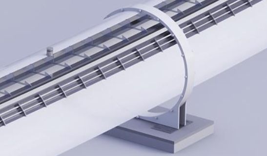
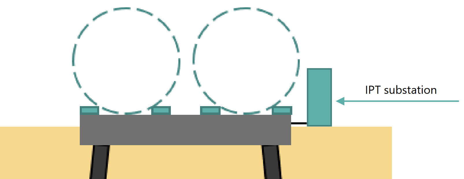
1.6 Guideway Power, Communication and Electronics
Characteristic | Performance |
Communication network | Fiber optics and antenna’s |
Vehicle charging | Contactless Inductive Power Transfer (IPT) |
IPT substation power | Installed to supply approx. 2 MW per km |
IPT substation intermediate distance | Context dependent |
Specification | Value |
Medium voltage power lines | 52 kV |
Low voltage power lines | 230 V |
IPT substation dimensions | H = 1 m ; W = 1 m ; L = 0.5 m |
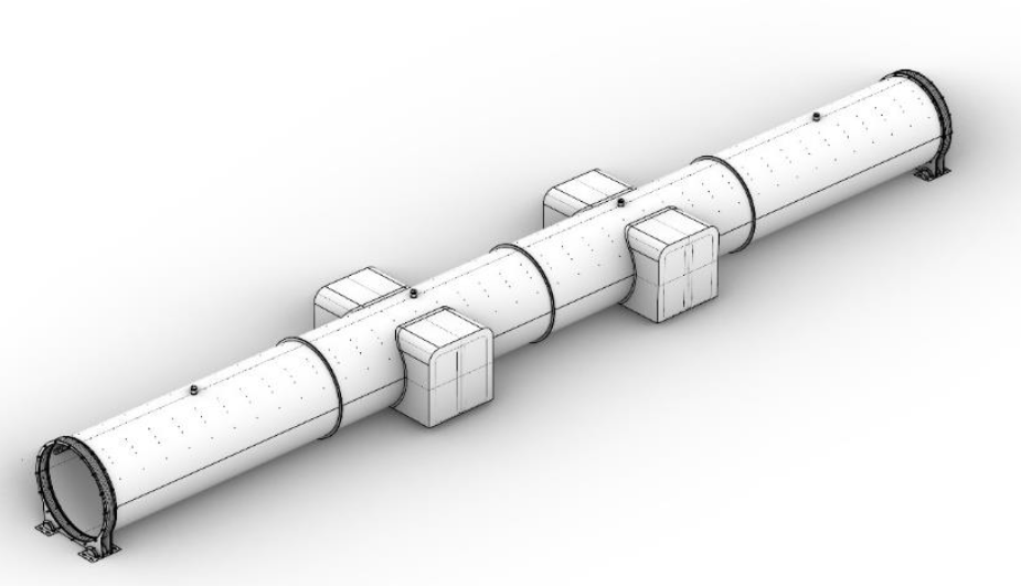
1.7 Vacuum Pumps
Characteristic | Performance |
Pump power | 1 kW/km for retention ; 22 kW/km for pump down |
Pump down time | 15 hours |
Intermediate pump station distance | 1 every 35 km for retention ;
1 every 1 km for pump down
pump down stations can be employed as mobile units |
Operating pressure | 1 mbar |
Leak rate | 660 Pa*L/s (Guideway = 50% ; Airlocks = 50%) |
Pump rate (retention) | 660 Pa*L/s |
*All values consider a one-way linear guideway
Specification | Value |
Pump down station dimensions | L = 6 m ; H = 2.5 m ; W = 2.5 m (Half container) |
Pump down station weight | 6,000 kg |
Retention station dimensions | L = 6 m ; H = 2.5 m ; W = 2.5 m (Half container) |
Retention station weight | 6,000 kg |
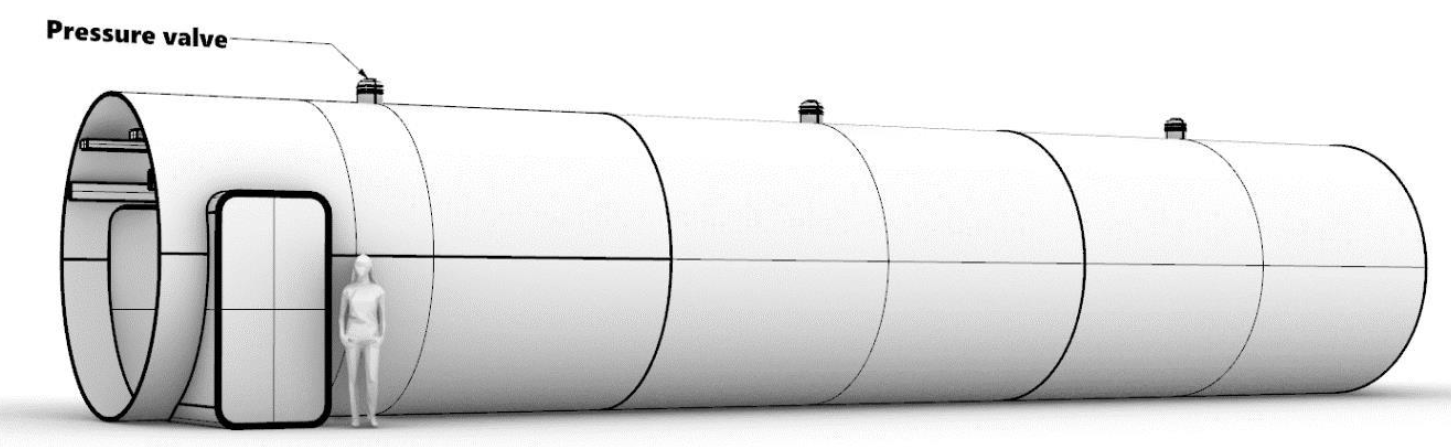
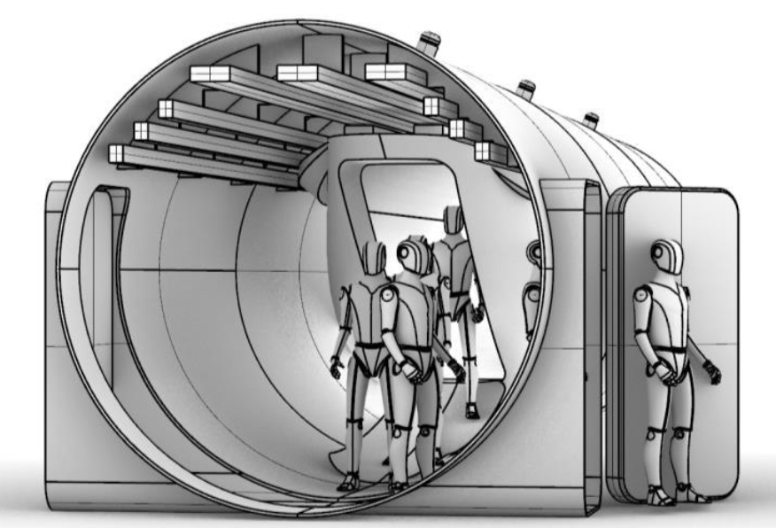
1.7 Emergency Exit
Characteristic | Performance |
Intermediate distance | 500 m |
Guideway pressurization time
(from 0.001 bar) | 4 s to 0.063 bar (6.3 kPa Armstrong limit)
35 - 40 s to 0.6 bar (breathing without masks)
60 - 90 s to 1 bar |
Emergency deceleration | 0.8 g or 8 m/s² |
Segmentation doors placement | Segmentation doors are placed at the outputs of a switch. This is done to:
1. keep other route segments operational,
2. allow vehicles in the route segment that has an emergency, to travel towards a nearby hub. |
Segmentation doors intermediate distance | *Context dependent |
Requirement per segment | Each segment requires a vacuum station
Each segment requires (a) release valve(s) |
*All values consider a one-way linear guideway
Specification | Value |
Segmentation doors diameter | Internal = 3.5 m ; External = Unknown |
Emergency exit doors dimensions | H = 2.2 m ; W = 1.42 m |
Release valves | 30 per km |
Valve inlet size | 15 cm |
2. Civil Infrastructure
A description of Civil Infrastructure Components
Disclaimer: The engineering related to the civil infrastructure is NOT part of Hardt’s core focus. In practice, the engineering and development of the required civil infrastructures will be out-sourced to civil engineering firms. For completeness, an indicative representation of the required civil infrastructure components is provided here.
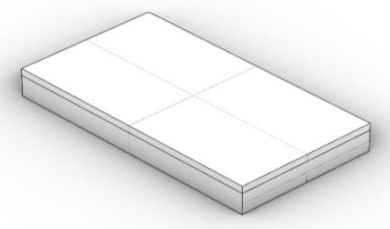
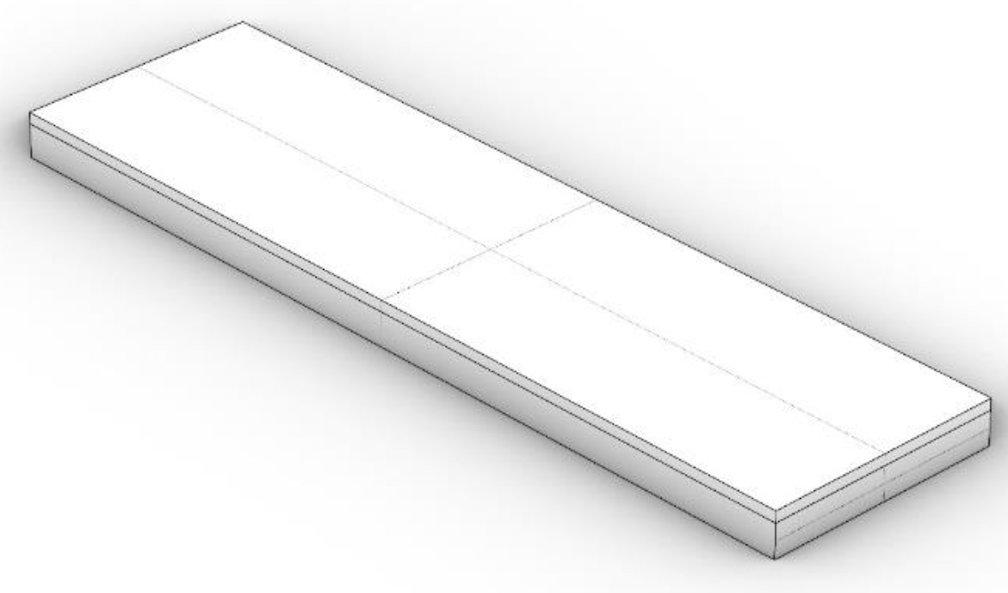
2.1 Emergency Exit
Characteristic | Performance |
Material | Concrete |
Span | <20 m |
Construction method | Off-site production in molds |
Specification | Value | |
Type | One-way | Two-way |
Weight | 15 tons | 30 tons |
Width | 2 m | 2 m |
Length | 4 m | 8 m |
Height | 1 m | 1 m |
Volume | 8 m² | 16 m² |
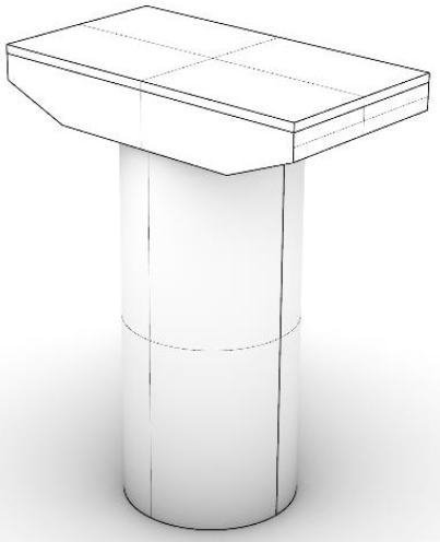
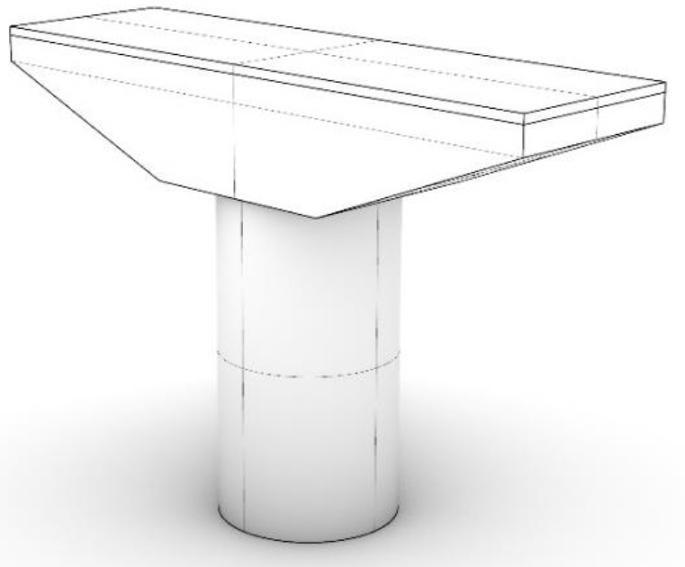
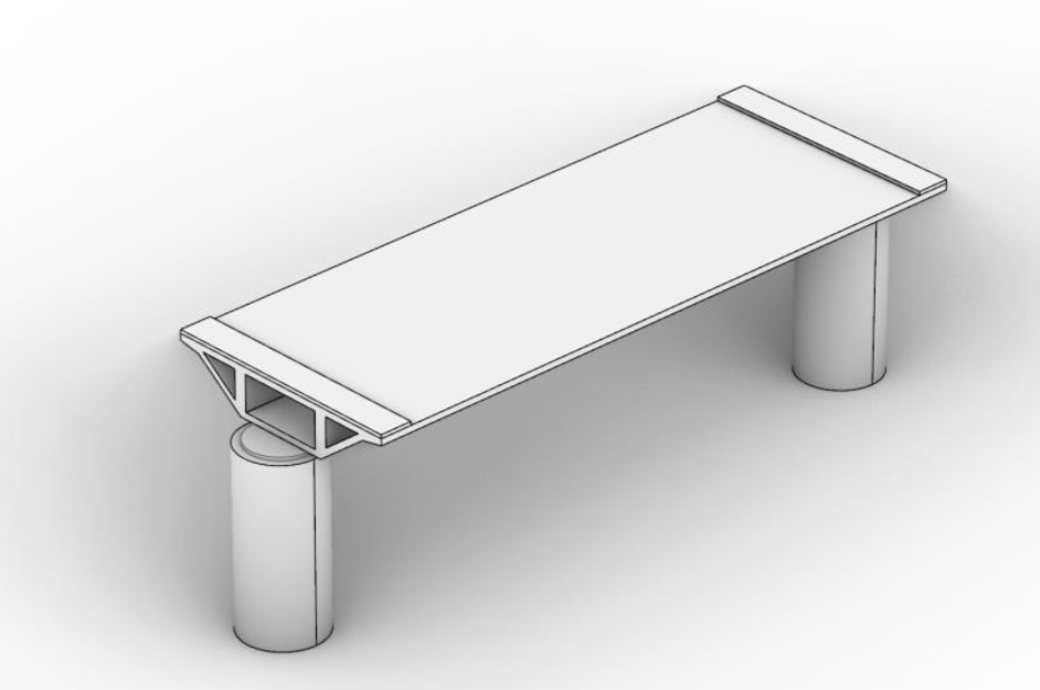
2.2 Elevated
Characteristic | Performance |
Material | Concrete |
Span | <20 m |
Crossing height | 5 m (vehicle below 5 m can cross) |
Max. height | 10 m |
Construction method | All components except for the pillar are produced off-site in molds |
Specification | Value | |
Type | One-way | Two-way |
Total weight (H = 5 m) | 80 tons | 200 tons |
Pillar diameter | 1.8 m | 1.5 m |
Width (Elevated Section) | 4 m | 8 m |
Length (Elevated Section) | 2 m | 2 m |
Height (Elevated Section) | ~1 m | ~2 m |
2.3 Bridge & Tunnel
Bridge Characteristic | Performance |
Span | >20 m |
Height | >10 m |
Material | Concrete & Steel |
Bridge type | Bridges are custom and will be designed depending on the location and obstacle |
Construction method | Location dependent |
Tunnel Characteristic | Performance |
Segment length | 20 m |
Lining material | Concrete |
Construction method | Location dependent (cut-and-cover or boring machines) |
Tunnel Characteristics | Performance | |
Tunnel Type | One-way | Two-way |
Internal Diameter | 4.2 m | 10 m |
Internal Diameter | 10 m | 11 m |
Wall Thickness | 0.4 m | 0.5 m |
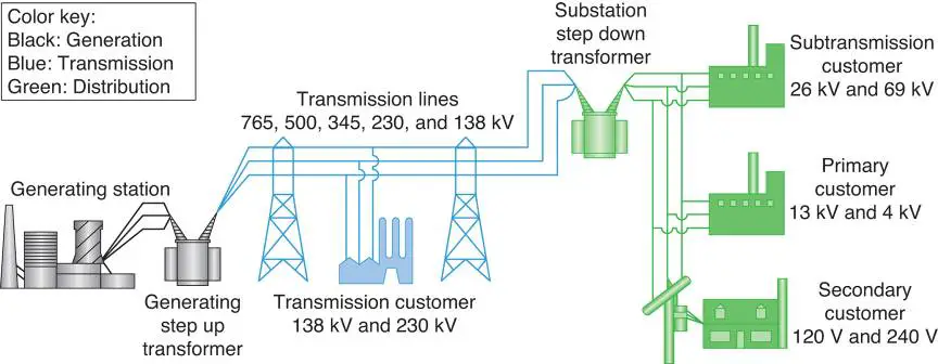
2.4 Electric Infrastructure
Characteristic | Performance |
Transmission tower intermediate distance | ~500 m |
Electrical substation intermediate distance | ~50 km |
Main power consumer | IPT substations |
Specification | Value |
Substation power electronics | ~380 kV to ~52 kV |
High voltage power lines | ~380 kV |
Medium voltage power lines | ~52 kV |
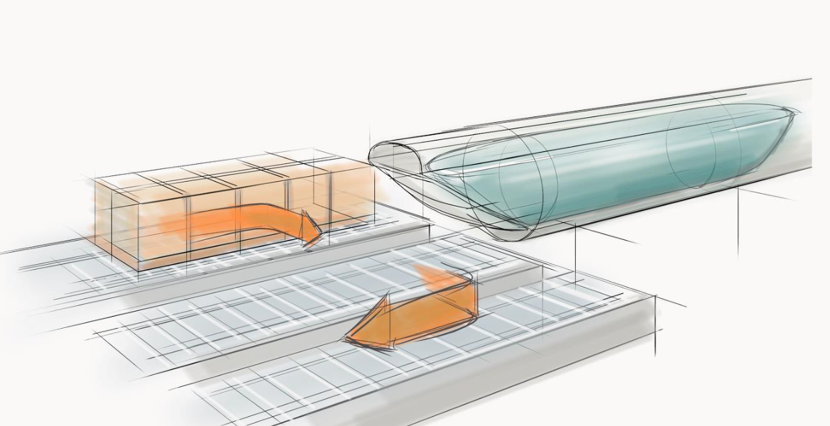
3. Vehicle
The design and specifications of Vehicle Components
3.1 Passenger Vehicle
Characteristic | Performance |
Payload | 40 Passengers |
Doors | 6 (4 embarking and 2 emergency doors) |
Turnaround time | 4 min |
Vehicle operation | Autonomous |
Propulsion power | 3 MW |
Propulsion efficiency | ~90% |
Cruising power consumption | 665 KW (at 700 kph) |
Operational drag (at 700 kph) | 3100 N (Aerodynamic - 1450 N ; Magnetic = 1650 N) |
Battery power | 640 kWh |
Acceleration | Max. 2.0 m/s² ; Avr. 1.1 m/s² (to 700 km/h) |
Deceleration | Max. 8.0 m/s² ; Avr. 1.5 m/s² |
Vehicle tilt angle | 6 °C (technology under development, expected between 0° and 13°) |
Operational airgap | 15 mm |
Magnetic lift-over-drag | 150 |
Operational pressure | 1 mbar |
Cabin pressure | 1 bar |
Monocoque material | Carbon Fiber |
Bogies material | Aluminium |
Specification | Performance |
Total length | 24 m |
Total weight | 25,000 kg |
External diameter | 2.5 m |
Frontal area | 5.73 m² |
Door dimensions | H = 2.2 m ; W = 1.4 m |
Mass Breakdown | Value |
Total weight | 25,000 kg |
Payload - subtotal | 8,600 kg (incl. cabin) |
Main body - subtotal | 3,200 kg |
Monocoque | 1,100 kg (1 x 1,100 kg) |
Bogies | 2,100 kg (7 x 300 kg) |
Tractive system - subtotal | 10,000 kg |
Levitation | 3,400 kg (42 x 80 kg) |
Propulsion | 1,700 kg (28 x 60 kg) |
Guidance | 1,700 kg (42 x 40 kg) |
Emergency breaking | 3,200 kg (26 x 120 kg) |
Battery - subtotal | 3,200 kg |
3.1 Passenger Vehicle
Characteristic | Performance |
Payload | 14 Euro Pallets |
Doors | 2 |
Turnaround time | 6 min |
Vehicle operation | Autonomous |
Propulsion power | 3 MW |
Propulsion efficiency | ~90% |
Cruising power consumption | 665 KW (at 700 kph) |
Operational drag (at 700 kph) | 3100 N (Aerodynamic - 1450 N ; Magnetic = 1650 N) |
Battery power | 640 kWh |
Acceleration | Max. 2.0 m/s² ; Avr. 1.1 m/s² (to 700 km/h) |
Deceleration | Max. 8.0 m/s² ; Avr. 1.5 m/s² |
Vehicle tilt angle | 6 °C (technology under development, expected between 0° and 13°) |
Operational airgap | 15 mm |
Magnetic lift-over-drag | 150 |
Operational pressure | 1 mbar |
Cabin pressure | 1 bar |
Monocoque material | Carbon Fiber |
Bogies material | Aluminium |
Specification | Performance |
Total length | 24 m |
Total weight | 25,000 kg |
External diameter | 2.5 m |
Frontal area | 5.73 m² |
Door dimensions | H = 2.2 m ; W = 1.8 m |
Mass Breakdown | Value |
Total weight | 25,000 kg |
Payload - subtotal | 8,600 kg (incl. cabin) |
Main body - subtotal | 3,200 kg |
Monocoque | 1,100 kg (1 x 1,100 kg) |
Bogies | 2,100 kg (7 x 300 kg) |
Tractive system - subtotal | 10,000 kg |
Levitation | 3,400 kg (42 x 80 kg) |
Propulsion | 1,700 kg (28 x 60 kg) |
Guidance | 1,700 kg (42 x 40 kg) |
Emergency breaking | 3,200 kg (26 x 120 kg) |
Battery - subtotal | 3,200 kg |
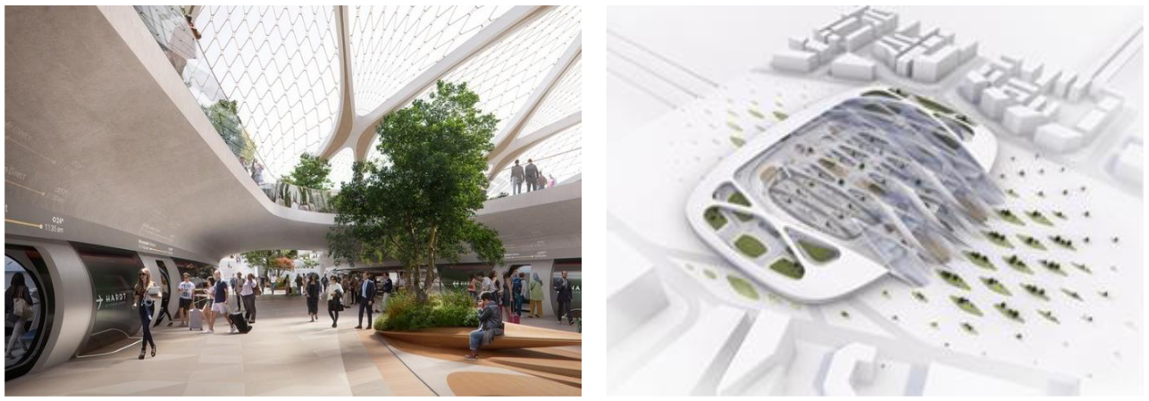
4. Hubs
The design and specifications of Hub Components
4.1 Passenger Hub
Characteristics | Performance |
Terminal switch length | 160 m |
Delta length | 60 m to 90 m |
Platforms per delta | 2 |
Operating pressure | 100 Pa |
Platform length | 40 m |
Platform width | 7 m |
Interface guideway type | Passenger Hub | Cargo Hub | Depot Hub |
Amount of airlocks | 4 | 1 | 1 |
total turn-around time | 4 min | 6 min | n/a |
Arrival process | 1 min | 1 min | 1 min |
(Dis-)embarking / (Un-)loading process | 2 min | 4 min | 4 min |
Departure process | 1 min | 1 min | 1 min |
Capacity per platform | 15 veh/h | 10 veh/h | 10 veh/h |
Acknowledgements